


3-39
The RIC must be connected to the host panel via RUI cabling. This section explains how
to wire the two together, and how to set up a system with multiple transponders connected
to the same host panel.
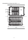
RUI cabling can be accomplished either through Class A or Class B wiring.
Class A wiring allows transponder cabinets to communicate with the FACP even in the
event of an open circuit somewhere in the loop. Class A wiring requires that two wires are
routed from the CPU motherboard to each RIC, and then back again to the CPU
motherboard.
Class B wiring allows “T” tapping, and therefore requires less wiring distance per
installation than Class A. Additionally, Class B wiring does not require end-of-line
resistors, because each RIC communicates directly to the CPU.
Make sure these prerequisites are accounted for before wiring:
• AS1670 allows the loss of a maximum of 40 detectors/addressable devices to be
caused by a single fault.
• All transponder cabinets are installed within 2500 feet (762 m) of the FACP.
• Conductors test free of all grounds.
• All wires are between 12 (3.309 mm
2
) and 18 AWG (0.8321 mm
2
), or as the
local code dictates.
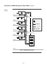
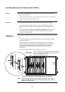
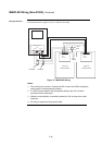
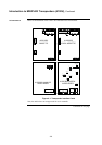
To connect the RUI card to RICs using Class A wiring, read the following instructions
and refer to Figure 3-7, on the next page.
1. Route wire between 0.75 mm
2
and 4 mm
2
from the + (TB1-8) and - (TB1-6)
terminals on the Comms “A” block of the 562-856/565-217 RUI card to the
TB1-8 (+) and TB1-6 (-) terminals on the 565-233 RIC.
2. Route wire from the first RIC to the next one. Repeat for each transponder
cabinet within 2500 feet (762 m).
3. Route wire from TB1-7 (+) and TB1-5 (-) on the last RIC to + (TB1-4) and -
(TB1-2) on the Comms “B” block of the 562-856/565-217 RUI card.
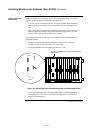
To connect the RUI card to RIC II cards using Class B wiring, read the following
instructions and refer to Figure 3-7, on the next page.
1. Route wire between 0.75 mm
2
and 4 mm
2
from the + (TB1-8) and - (TB1-6)
terminals on the Comms “A” block of the 562-856/565-217 RUI card to the
TB1-8 (+) and TB1-6 (-) terminals on the 565-233 RIC.
2. Route wire from the first RIC to the next one. Repeat for each transponder
cabinet within 2500 feet (762 m).
Continued on next page
MINIPLEX Wiring (Non-4100U)
Overview
Wiring
Configurations
Class A Wiring
Class B Wiring