


7-5
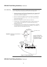
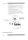
To connect the SPS to appliances using Class B wiring, read the following instructions
and refer to the figure below.
1. Route wire (between 0.75 mm
2
and 4 mm
2
) from the B+, B- outputs on TB2 of
the SPS to the appropriate inputs on a peripheral notification appliance. Use
NAC1, NAC2, or NAC3, as configured.
2. Route wire from the first appliance to the next one. “T” tapping is not allowed.
Repeat for each appliance.
3. Route wire from the last appliance to the supplied EOLR or a 4081-9008 EOL
Harness (10 K Ohm, ½ W; brown/black/orange).
4. Repeat steps 1 through 3 for each NAC output you want to use.
5. Leave the 378-030 EOL Resistor (10 K Ohm, ½ W; brown/black/orange) on
each unused circuit. The circuit must connect “B+” to “B-” terminals.
6. If the appliance/device to be used does not have an integral diode, a blocking
diode must be fitted between the incoming +ve wire and the +ve terminals of the
device with cathode to the device.
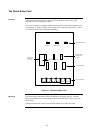
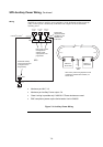
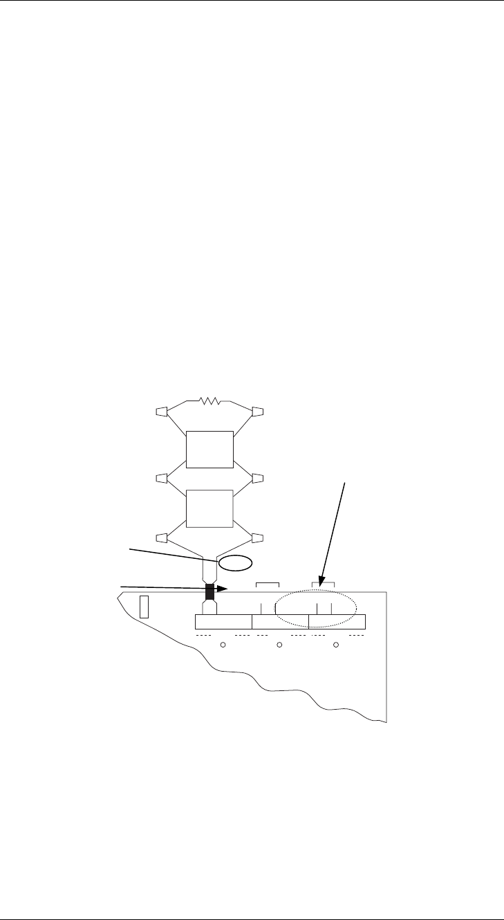
The illustration below shows Class B wiring.
P1
3
2
1
B+ B- A+ A-
TYPICAL
APPLIANCE
RED BLK
NAC1
B+ B- A+ A-
NAC1
B+ B- A+ A-
NAC1
LED1 LED2 LED3
TYPICAL
APPLIANCE
10K 1/2W (133-894)
NAC2 NAC3
RED RED
RED RED
Figure 7-3. Class B Wiring
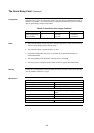
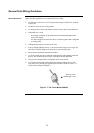
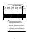
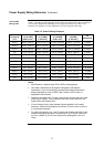
Before wiring from any type of power supply to notification appliances, check Tables 7-1
and 7-2 for wiring distances.
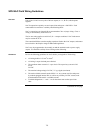
Class B NAC Wiring
Power Supply Wiring Distances
Overview
Important: Conductors must test free of
all grounds.
0.75 mm
2
to 4 mm
2
BLK
BLK
BLK
4081-9008 EOL Harness
Leave the 378-030 EOL
Resistor (10 K Ohm, ½ W;
brown/black/orange) on
unused B+/B- terminals
Ferrite bead
required for CE
compliance. Use
SX0005 or kit
4100-5129.