


2-21
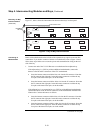
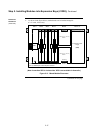
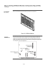
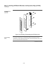
Below is an illustration of a LED/switch bay from the user’s perspective.
Figure 2-14. LED/Switch Modules
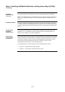
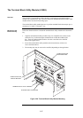
The LED/switch controller card is a 4100 slave that mounts behind two LED/switch
modules. The LED/switch controller handles up to 64 switches and 64 LEDs on the
modules and communicates their status to the 4100 CPU. When a button is pressed on a
module, the controller acknowledges the signal and reacts according to how that switch
was configured via the 4100 Programmer.
GND1
LED1
P2
12
SW1
1
2
3
4
5
6
7
8
P1
COMM
LOSS
P3
12
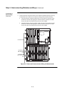
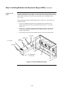
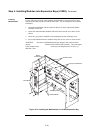
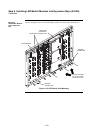
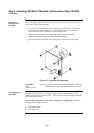
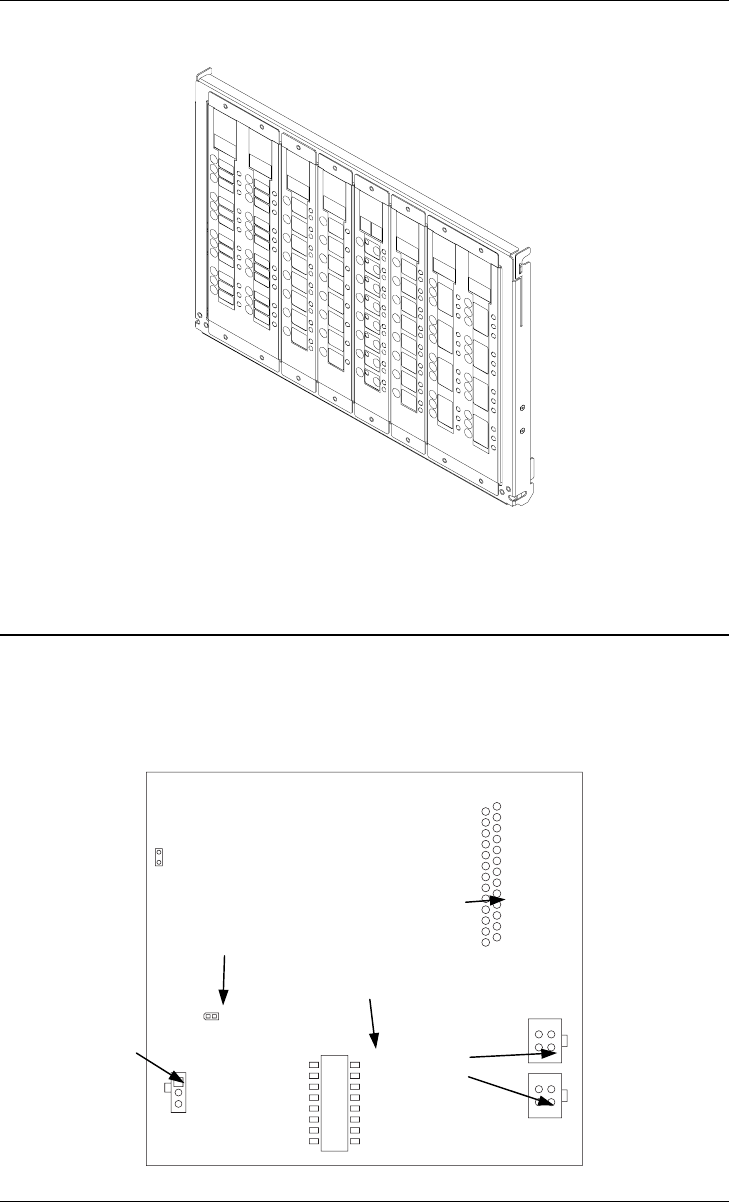
Figure 2-15. LED/Switch Controller
Continued on next page
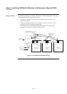
Step 6. Installing LED/Switch Modules into Expansion Bays (4100U),
Continued
The LED/Switch
User Interface
LED/Switch
Controller Card
LED/SWITCH DISPLAY
CONNECTOR
(P4; reverse side)
POWER/COMMS
CONNECTORS
(P2)
(P3)
COMM LOSS LED (LED1)
ADDRESS DIP
SWITCH (SW1)
REMOTE ANNUNCIATOR
JUMPER (P1)