


6-3
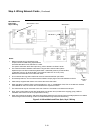
• +24V Sig is used to supply the NACs. It can be made accessible by
configuring a NAC as an aux power output (normally energized). The PDI
has a 24V Sig bus that is only powered when an SPS is plugged directly on
to it. (Not in standard configuration). The 4100 MXP is the only Australian
approved card that takes power from this bus. All other cards draw power
from +24V Card.
• The battery circuit is supervised every 29 seconds. The battery test (custom
control) is for 1 hour once per week.
• The battery is connected to the charger but is normally disconnected from the
bulk supply. During mains fail, and the 1 hour battery test, the battery gets
connected to the bulk supply.
• The IDNet output is 30V in the normal condition as is used to prolong battery
standby. When it is necessary to activate large numbers of output devices on
IDNet peripherals (such as piezo sounders), the output voltage is increased
to 35V to provide sufficient voltage at the end of line to activate the piezo.
The higher voltage state is an alarm condition for the purpose of standby
battery calculation.
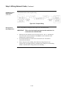
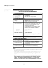
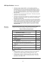
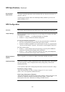
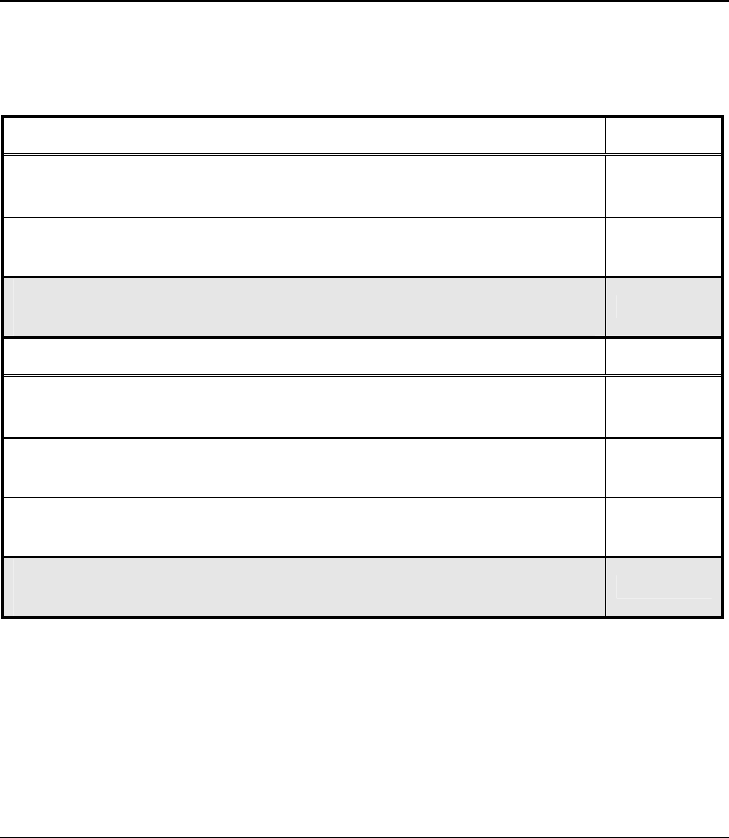
The following table summarizes battery standby capabilities for the SPS. Voltage
assumed is 24 V, which is the rated battery voltage for lead-acid type batteries.
Table 6-2. SPS Current Specifications
Standby Conditions Current
• No alarms (NACs normal)
• IDNet LED ON, no IDNet devices connected
175 mA
Add to above for each additional set of 50 IDNet devices in
standby, with IDNet at 30 V
40 mA
Total current for fully loaded IDNet channel (250 devices) in
standby
375 mA
Alarm Conditions Current
• 3 NACs ON
• IDNet LED ON, no IDNet devices connected
185 mA
Add to above for each set of 50 IDNet devices in alarm, 20
LEDs ON
80 mA
Add to above for each set of 50 IDNet devices in alarm, LEDs
OFF
50 mA
Total current for a fully loaded IDNet channel (250 devices) in
alarm, 20 LEDs ON
475 mA
Notes:
• Additional standby conditions: Trouble relay activated, power trouble LED
on, IDNet LED on, battery charger off, auxiliary power load = 0 mA
• Additional alarm conditions: Trouble relay activated, power trouble LED
on, IDNet LED on, battery charger off, auxiliary power load = 0 mA, NAC
alarm load = 0 mA, IDNet = 35 V
Continued on next page
SPS Specifications, Continued
SPS Current
Consumption