


13
RT-PRC005-EN
MA'
MA'
SA'
SA'
RA'
RA'
OA
OA
OA
OA
RA'
68°F DB,
67°F WB
75°F DB,
52% RH
MA' 72.2°F DB
65°F WB
SA'
47°F DB
SA
SA
REHEAT
SA
73°F DB
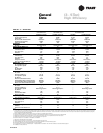
Selection
Procedure
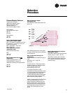
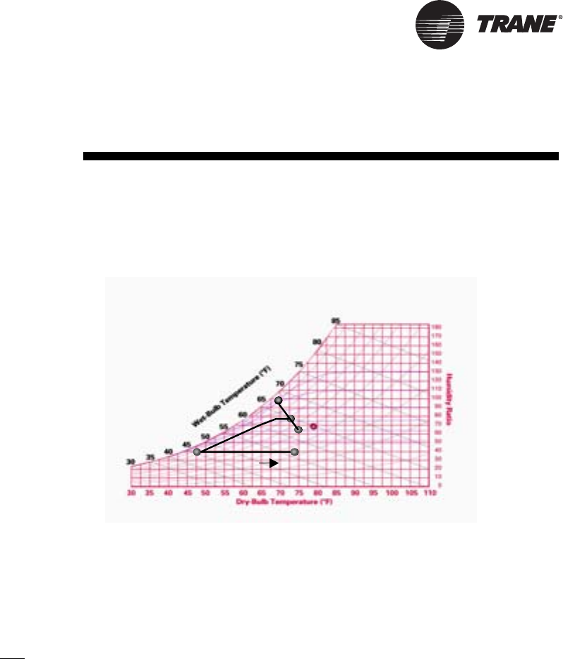
Dehumidification Selection
Typical 10 ton THC120A
2000 cfm Total Supply airflow
800 cfm Outside Air (40%)
1200 cfm Return Air
0.41” External Static Pressure
OA Conditions
Part load day and raining
68°F db
67°F wb
RA’ conditions
75°F db
63°F wb
Step 1: Determine the mixed/
entering air condition (MA’)
MA’ = (% outside air*outside air dry-bulb
temperature) + (% return air*return air
dry-bulb temperature)
MA’ = (0.40*68°F) + (0.60*75°F)
MA’ = 72.20°F db
Note: Repeat for wet-bulb
temperature (wb).
Plot on psychrometric chart.
MA’
72.2°F db
65°F wb
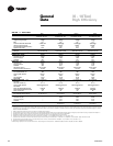
Step 2: Determine leaving
unit
temperature
Leaving Unit Temperature = SA’
Utilize the TOPSS™ program to
determine the leaving unit temperature.
45°F db
44°F wb
43°F dp
Step 3: Determine reheat
temperature rise
Go to PD-66 for reheat temperature rise:
26.7°F db
Note: Reheat temperature rise is based
on supply airflow and leaving evaporator
coil temperature.
Step 4: Determine leaving unit
temperature
Reheat temperature (obtained in step 3)
+ SA’
26.7°F db + 47°F = 73.7°F db
SA=73.7°F
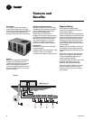
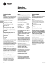
Consider Chart C-1. If the space relative
humidity is equal to or above the space
relative humidity setpoint, the
Dehumidification option will:
• Energize compressor or both
compressors (2 stage compressor units).
• Hot gas reheat valve is energized and
hot gas is diverted to the reheat coil.
• Dehumidification/reheat is terminated
when space humidity is reduced to 5%
below relative humidity setpoint.
At MA’, air enters the RTU. The RTU filters,
cools, and dehumidifies the air as it
moves through the evaporator coil. Air
leaves the evaporator coil saturated at
the preset dew point condition (SA’) and
is reheated by the hot gas reheat coil to
deliver 73.7°F (SA) supply air to the
space.
Chart C-1
Step 5: Determine static pressure
drop add for reheat
Table PD-61 shows a static pressure drop
of 0.09” wc 0.41”+ 0.09” = 0.5” wc
Table PD-57 indicates that a standard
motor and field installed low static drive
kit is needed for this airflow and static
pressure range.