


12 RT-PRC005-EN
Cooling Capacity
Step 1
Calculate the building’s total and sensible
cooling loads at design conditions. Use
the Trane calculation methods or any
other standard accepted method.
Factors used in unit selection:
A
Total Cooling Load: 59 MBh
B
Sensible Cooling Load: 40 MBh
C
Airflow: 2000 cfm
D
Electrical Characteristics: 460/60/3
E
Summer Design Conditions: Entering
Evaporator Coil: 80 DB, 67 WB Outdoor
Ambient: 95
F
External Static Pressure: 0.36 in. wg
G
Downflow Configuration
H
High Efficiency
I
Economizer
Step 2
As a starting point, a rough determination
must be made of the size of the unit. The
final selection will be made after
examining the performance at the given
conditions. Divide the total cooling load by
nominal BTUH per ton (12 MBh per ton);
then round up to the nearest unit size.
59 MBh / 12 MBh = approx. 5 tons
Step 3
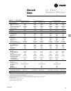
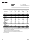
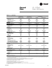
Table PD-15 shows that a THC060A4 has
a gross cooling capacity of 62.4 MBh and
48.4 MBh sensible capacity at 2000 cfm
and 95 DB outdoor ambient with 80 DB,
67 WB air entering the evaporator.
To Find Capacity at Intermediate
Conditions Not in the Table
When the design conditions are between
two numbers that are in the capacity
table, interpolation is required to
approximate the capacity. Note:
Extrapolation outside of the table
conditions is not recommended.
Step 4
In order to select the correct unit which
meets the building’s requirements, the
fan motor heat must be deducted from
the gross cooling capacity. The amount of
heat that the fan motor generates is
dependent on the effort by the motor -
cfm and static pressure. To determine the
total unit static pressure:
External Static (duct system)
0.36 wg
Standard Filter 1 in. 0.15 wg
from Table PD-61
Economizer 0.18 wg
(100% Outside Air) from Table
PD-73
Electric Heater Size 6 kW 0.056 wg
from Table PD-61
(reference “Heating Capacity” section on
this page for determination of heater
size)
Total Static Pressure 0.75 wg
Note: The Evaporator Fan Performance
Table PD-46 has deducted the pressure
drop for a 1 in. filter already in the unit
(see note below Table PD-24). Therefore,
the actual total static pressure is 0.75 -
0.15 (from Table PD - 61) = 0.60 wg.
With 2000 cfm and 0.60 wg.
Table PD-46 shows .90 bhp for this unit.
Note below the table gives a formula to
calculate Fan Motor Heat,
2.829 x bhp + .4024 = MBH.
2.829 x .83 + .4024 = 2.75 MBH.
Now subtract the fan motor heat from
the gross cooling capacity of the unit:
Net Total Cooling Capacity
= 62.4 MBH - 2.95 = 59.45 MBH.
Net Sensible Cooling Capacity
= 48.4 MBH - 2.95 = 45.45 MBH.
Step 5
If the performance will not meet the
required load of the building’s total or
sensible cooling load, try a selection at
the next higher size unit.
Heating Capacity
Step 1
Calculate the building heating load using
the Trane calculation form or other
standard accepted method.
Step 2
Size the system heating capacity to
match the calculated building heating
load. The following are building heating
requirements:
A
Total heating load of 15 MBH
B
2000 cfm
C
460 volt/3 phase Power Supply
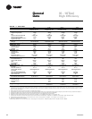
The electric heat accessory capacities
are listed in Table PD-62. From the table,
a 6 kW heater will deliver 20.48 MBH at
480 volts. In order to determine capacity
at 460 volts, the heater voltage
correction factor from Table PD-63 must
be used. Therefore, 20.48 MBH x .9118
(voltage correction factor) = 18.80 MBH.
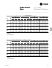
Air Delivery Selection
External static pressure drop through
the air distribution system has been
calculated to be 0.60 inches of water.
Enter Table PD-46 for a THC060A4 at
2000 cfm and 0.60 static pressure. The
standard direct drive motor will give the
desired airflow at a rated bhp of 0.90
and 998 rpm.
Selection
Procedures