II. Control System
4. Installation
II
24
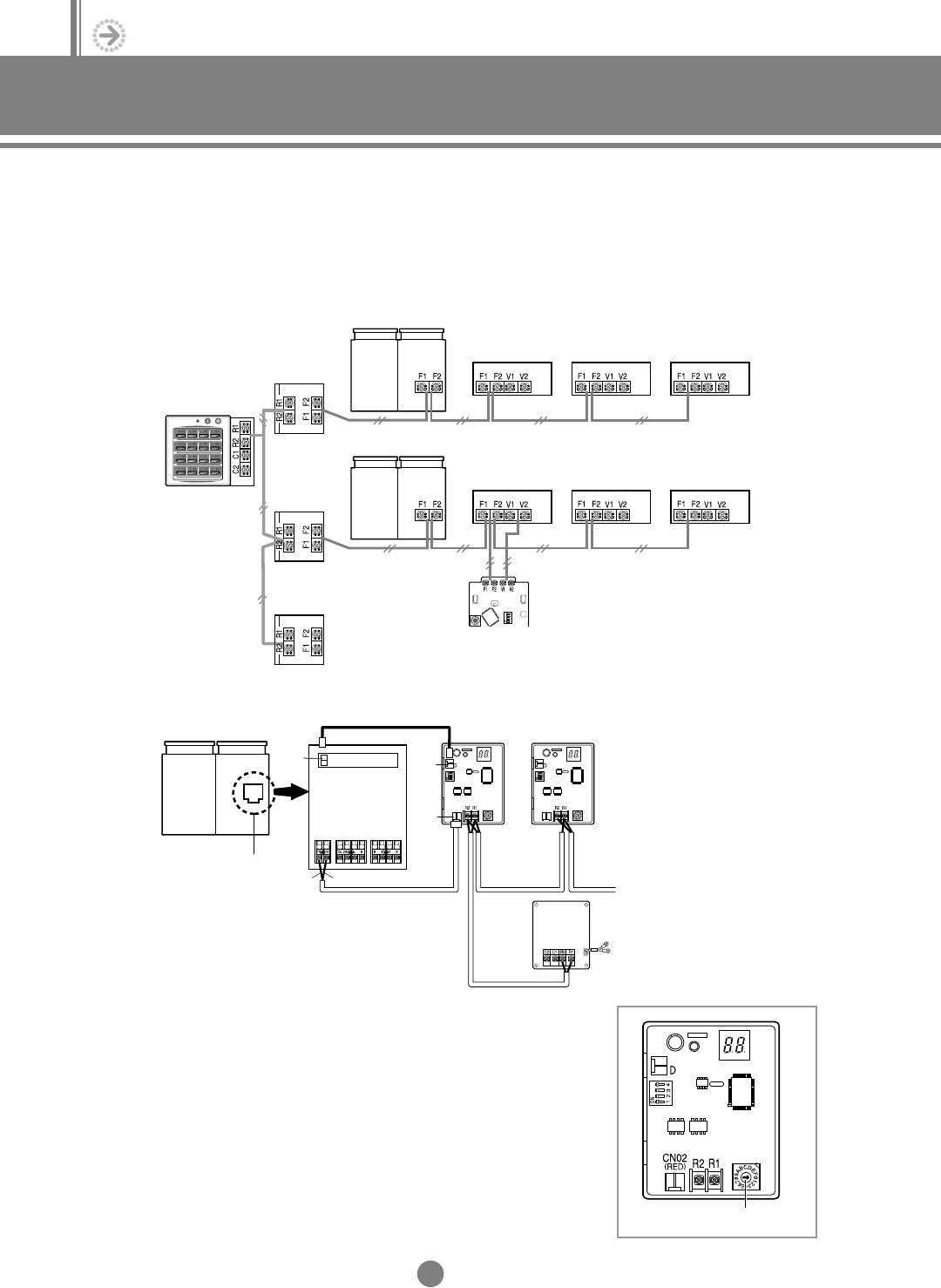
(3) Wiring diagram
◆ Each outdoor unit connected to the same centralized controller has its own transmitter.
◆ Distance between the centralized controller and the last transmitter should be
1000 meters or less.
(4) Transmitter installation
(5) Assigning address
◆ Turn the arrow of rotary switch on the transmitter to
appropriate position. Transmitters controlled with the same
centralized controller must have different addresses.
Outdoor unit 1
Transmitter 1
Transmitter 2
Transmitter 3
Centralized
controller
Indoor unit 1 Indoor unit 2 Indoor unit 3
Outdoor unit 2
Indoor unit 4
Wired remote controller
Indoor unit 5 Indoor unit 6
Transmitter 1
Transmitter 2
CN01
(BLUE)
CN12
(BLUE)
CN02
(RED)
Transmitter 3
AC power supply
Centralized
controller
Outdoor unit PCB
Red
Blue
Transmitter rotary switch
DVM E-D/B(chapter2)-E<03759 3/21/02 7:33 PM Page 24


