V. Installation
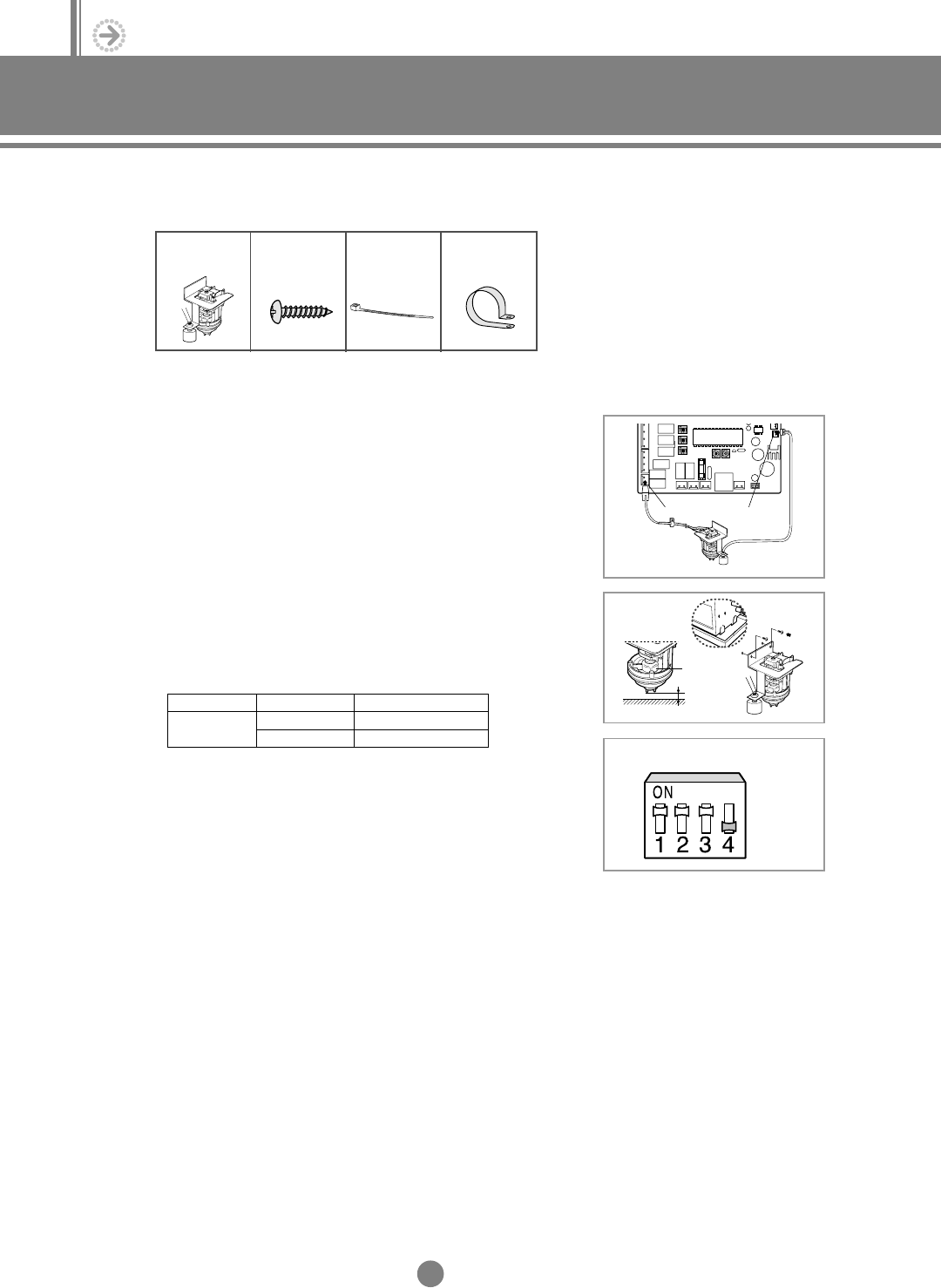
5. Drain pump installation-optional
(Example;Low-silhouette duct type)
V
22
K1 K2 K3 K4
SW03
Drain pump
Drain pump
7mm
Bottom of the drain pan
Float switch
5-1. Accessories
5-2. Accessories
Drain pump &
Float switch (1)
M4x12
Tapped screw
(4)
Cable-tie (2) Cable clamp
(2)
(1)
Connect the cable to the electrical component box as shown at
the figure.
(2) Screw the drain pump to the side of the indoor unit with two
screws.
(3) Adjust K4 DIP switch(SW03) to the "OFF" position.
◆
Wrap the drain tube outlet on the right and left side of
the indoor unit with an insulating materials.
NN
NN
oo
oo
tt
tt
ee
ee
◆
When installing the drain pump, leave a 7mm space
between the bottom of the drain pan and the drain pump.
NN
NN
oo
oo
tt
tt
ee
ee
◆
Connect the drain pump cable to yellow terminal(CN74)
and the float switch to black terminal(CN51).
NN
NN
oo
oo
tt
tt
ee
ee
Switch No.
K4
Switch Position
ON
OFF
Using Drain Pump
X
O
DVM E-D/B(chapter5)-E<03759 3/21/02 7:40 PM Page 22


