II. Control System
4. Installation
II
12
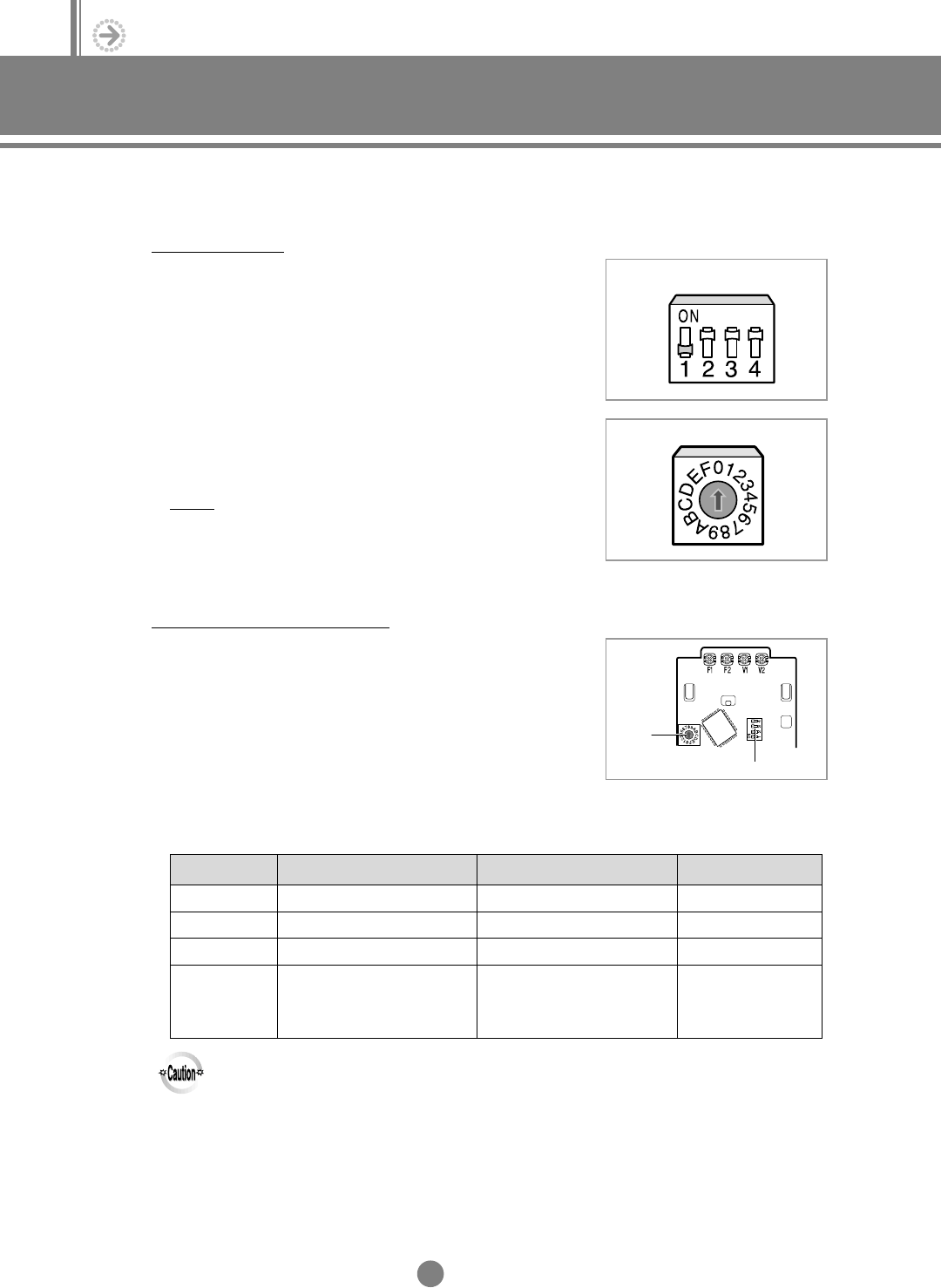
(3) Setting up option switches
Indoor unit PCB
1) Adjust K1 DIP switch(SW03) on the PCB to the “OFF”
position.
2) Turn the arrow of RMC rotary switch(SW01) to the
appropriate position.
Result
: It is controlled by a wired remote controller which has
the same address.
Wired remote controller PCB
1) Assign an address to the wired remote controller by turning
the arrow of rotary switch.
2) Adjust the DIP switch to appropriate position.
Refer to the table below.
RMC SW01
K1 K2 K3 K4
SW03
Rotary
Switch
DIP Switch
◆
The address of wired remote controller and the RMC
address of indoor units should be the same.
NN
NN
oo
oo
tt
tt
ee
ee
◆All indoor units you wish to control with wired remote controller must have the same RMC address.
◆Indoor units controlled with the same wired remote controller should be connected to the same
outdoor unit and must have different MAIN addresses.
◆If you would like to use the wired remote controller and the centralized controller together,
refer to page II-16.
Switch No. OFF
1
2
3
4
Cooling only
-
°C display
Can be used wired and
wireless remote controller
(Slave mode)
ON
Cooling and Heating
-
°F display
Can be used wired remote
controller only
(Master mode)
Original Position
ON
OFF
OFF
OFF
DVM E-D/B(chapter2)-E<03759 3/21/02 7:33 PM Page 12


