


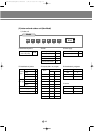

6.
Refrigerant system diagram
(Cooling only & heat pump)
6-1.
Refrigerant system diagram
6-2. Main parts status
73
73
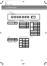
7. Piping and refnet
joint selection
7-1.
Refrigerant piping system diagram
7-2. Piping selection
7-3. Refnet joint selection
33
33
34
3. Functional parts and
safety devices
3-1. Outdoor unit
3-2. Super cooler
8
13
8.
Consideration for
outdoor unit selection
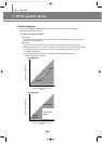
8-1.
Change of capacity depending
on refrigerant piping length
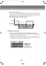
8-2.
Condition of operating
restriction
46
47
1. Unit selection
(with cooling load)
3. Connecting the indoor
unit refrigerant pipe
9.
Velocity of air flow &
temperature distribution
9-1. 1-way cassette type
9-2. 4-way cassette type
9-3. Wall-mounted type
9-4. Ceiling type
102
103
105
107
12. Electronic expansion
valve kit
12-1. Design
12-2. Status depending on the
combination
113
113
7.
Electric circuit diagram
7-1. 1-way cassette type
7-2. 4-way cassette type
7-3. Duct type
7-4. Wall-mounted type
7-5. Floor standing type
7-6. Ceiling type
74
76
78
80
82
84
8. Noise level
8. Noise level
8-1. Overall
8-2. Octave band level
86
87
10. Fan specifications
10-1.
Duct type(Low silhouette)
10-2.
Duct type(Built-in)
10-3.
Duct type(High pressure)
108
109
110
11. Panel
11-1. 1-way cassette type
11-2. 4-way cassette type
111
112
13. Options
2. Specification
2-1. 50Hz
2-2. 60Hz
4
6
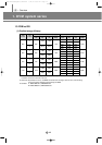
4. Capacity table
4-1. 50Hz
4-2. 60Hz
14
20
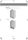
5. Dimension
5-1. Upward (2-FAN)
5-2. Onward
5-3. Upward (1-FAN)
5-4. Upward (Super cooler)
31
32
33
34
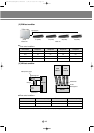
6.
Refrigerant system diagram
6-1. Cooling only
6-2. Heat pump
35
38
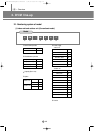
7.
Electric circuit diagram
7-1. Cooling only
7-2. Heat pump
42
44
9. Noise level
10. Options
IIVV
Outdoor
unit
1. Product
1-1. Preparation for installation
1-2. Deciding on where to install
the air conditioner
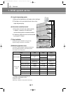
1-3. Space requirements for the
air conditioner
1-4. Accessories
1-5. Installation
2
3
4
8
11
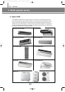
2. Panel
2-1. 1-way cassette type
2-2. 4-way cassette type
2-3. Duct type (Built-in)
13
15
16
5. Drain pump installation
5-1. Accessories
5-2. Installation
22
22
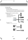
6. Wiring
6-1.
Overall system configuration
6-2.
Cable specification for outdoor unit
6-3.
Connection cord specification
6-4. Wiring diagram
6-5.
Connection cord wiring diagram
6-6.
Power wiring and communication
wiring configuration
6-7.
Communication cable connection
23
24
24
24
25
25
26
8.
Charge/recovery of refrigerant
8-1. Refrigerant charging
8-2.
Additional refrigerant amount
calculation method
8-3. Recovery of refrigerant
35
36
37
4. Drain hose installation
9. Testing operation
10.
Cautions for refrigerant leaks
VV
Installation
DVM E-D/B(chapter1)-E<03759 3/21/02 6:55 PM Page 3