


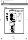
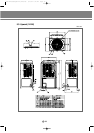
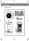
IV. Outdoor unit
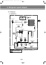
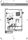
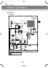
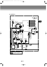
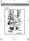
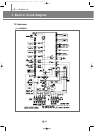
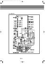
6. Refrigerant system diagram
IV
40
(3) Main parts status
1) Digital scroll compressor
The variable capacity type compressor to control the capacity up to 10 ~ 100% with 19 steps
2) Accumulator
To prevent the incoming of the liquid refrigerant to the compressor (prevention of liquid back).
3) Receiver
To reduce the noise by flowing the high pressure liquid refrigerant to the high pressure pipe and to control
the amount of refrigerant during the individual operation of indoor unit.
4) Solenoid valve (PWM)
It is installed at the top of digital scroll compressor and at the low pressure pipe, which is used for operating
the digital scroll compressor. When the valve is open, the digital scroll compressor keeps the state of
unloading.
5) Solenoid valve (HGBV)
When the low pressure gets lower, the valve is open by the low pressure safety device. The valve is open in
order to reduce the load at the start of compressor and when the system stops and then keep the balance of
low pressure.
6) Solenoid valve (LBV)
When the compressor is overheated, it actuates to lower the temperature of compressor for stable operation.
7) Solenoid valve (VBV)
The valve is open in order to reduce the load at the start of compressor and when the system stops and then
keeps the balance of low pressure.
8) High pressure switch
To stop the system for the system protection when the high pressure exceeds the set value.
9) Temperature sensor (DTS, Discharge Temperature Sensor)
It is the means to measure the refrigerant temperature of compressor outlet which is used as the data
for control of compressor.
10) Temperature sensor (COS, Condenser Out Sensor)
When heating, used for defrost control by sensing outdoor heat exchanger temperature.
DVM E-D/B(chapter4-2)-E<03759 3/21/02 7:40 PM Page 40