


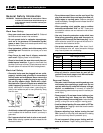
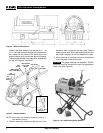
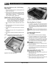
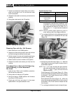
Figure 5B – No. 1460 Oil Pan Cover
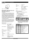
Mounting Machine To Bench
1. If a stand is not used, the machine should be
mounted to a stable bench. To mount the unit on a
bench, use four (4)
5
/
16
″ bolts in holes provided at each
corner of machine base. Base dimensions are shown
in Figure 2.
Failure to mount the threading machine to
a stable stand or bench may result in tipping and serious
injury.
Transporting Machine with
No. 1406 Stand
1. Install 1460 Oil Pan Cover to prevent oil spillage.
2. For ease of transporting, turn hand crank counter-
clockwise and fold stand into a compact package.
3. Lift handles (front and rear) and skid bars are provided
for transportation on stairways, over rough terrain
and in and out of trucks, vans and station wagons.
Use two persons on stairs.
4. The front handle is for control on stairs and wheel-
barrow like operation.
5. The rear handle is for an assist on stairs, lifting in and
out of vehicles and movement over flat surfaces in the
operational position.
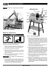
Transporting Machine with a Tow
Motor, Material Lift or Crane
1. Place tow motor forks below base of machine and
above cabinet or tray.
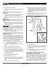
2. Loop a sling over a 2″ piece of pipe as shown in
Figure 6 and lift machine with a lift or crane.
3. Place a sling around machine and top stand rails
and lift machine with a material lift or crane.
Ridge Tool Company
7
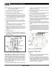
Mounting Machine to No. 1406 Folding
Wheel Stand
1. Raise rear handle of stand to a vertical position and
tighten mounting bolts.
2. Using hand crank, raise stand to its operating height.
Place machine on stand with carriage away from
wheels (Figure 4). Insert four
1
/
4
″ – 20 bolts through
rails into machine base. Tighten bolts.
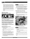
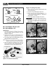
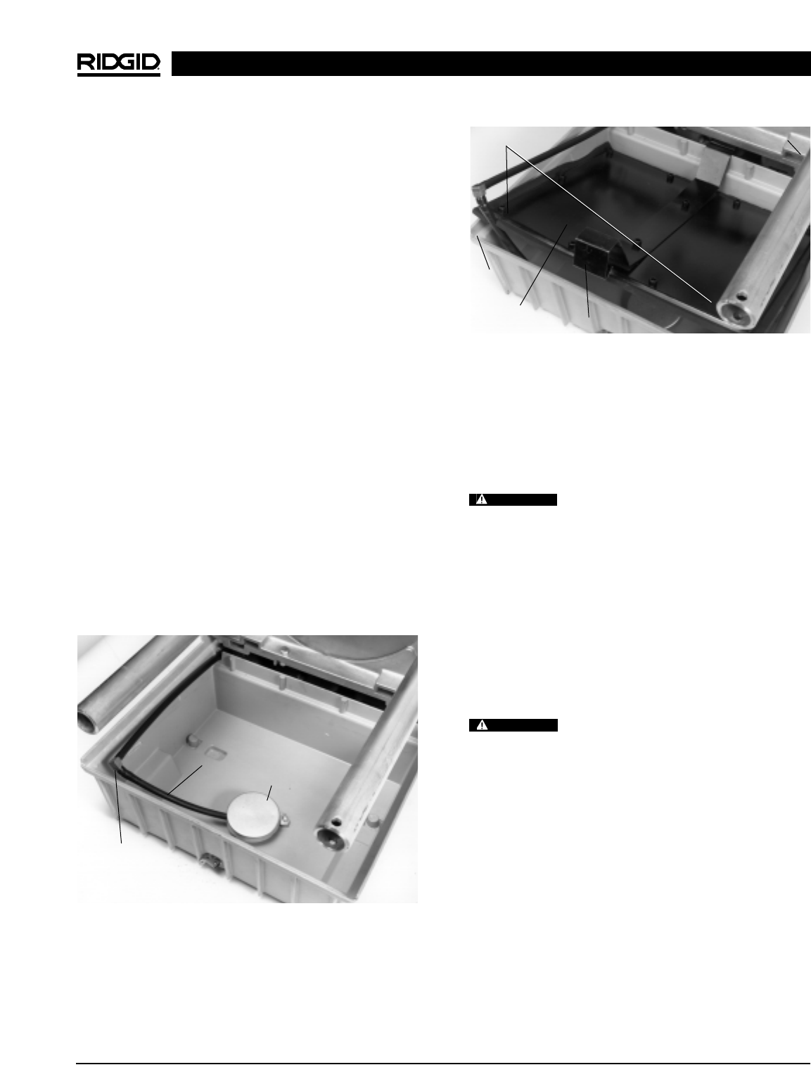
Installing No. 1460 Oil Pan Cover
NOTE! No. 1460 Oil Pan Cover installs in machine oil
reservoir and prevents oil spill during transporta-
tion. No. 1460 is shipped with No. 1406 Folding
Wheel Stand and is available as an accessory.
1. With oil reservoir drained, disconnect filter and oil
line.
2. Attach elbow fitting and oil line extension to existing oil
line (Figure 5A).
3. Reattach oil line to filter and the filter to reservoir
base.
4. Install oil pan cover with oil line positioned as in
Figure 5B.
5. Set chip pan in place and machine is ready for trans-
port.
NOTE! Chip pan will not lock into position. This is a re-
minder that the oil pan cover is installed.
Figure 5A – No. 1460 Oil Pan Cover
1822-I Pipe and Bolt Threading Machine
Oil Filter
Line Extension
Elbow Fitting
Rear Latch
Push
Oil Line
Notch
Oil Pan
Cover
Front Latch
WARNING
WARNING