


Ridge Tool Company
12
8. Move die head to UP position.
9. Release foot switch and remove your foot from the
housing.
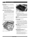
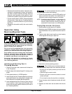
Removing Pipe From The Threading
Machine
1. Turn the control switch to the OPEN position. Depress
foot switch and machine will release the pipe.
2. Release foot switch and turn control switch to the OFF
position.
Never reach inside chuck cover while ma-
chine is connected to a power source. Fingers can be
crushed.
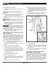
3. Slide the workpiece out of the Threading Machine,
keeping a firm grip on the workpiece as it clears the
Threading Machine.
To avoid injury from falling parts or equip-
ment tip-overs when handling long workpieces, make
sure that the end farthest from the Threading Machine is
supported prior to removal.
4. Clean up any oil spills or splatter on the ground sur-
rounding the Threading Machine.
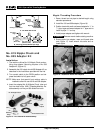
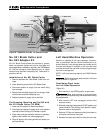
Installing Dies In Self-Opening Die Head
(Right Hand Only)
The No. 815A Self-Opening Die Head (Figure 10) for
right hand threads requires four sets of dies to thread pipe
ranging from
1
/
8
″ through 2″. One set of dies is required for
each of the following pipe size ranges: (
1
/
8
″), (
1
/
4
″ and
3
/
8
″), (
1
/
2
″ and
3
/
4
″) and (1″ through 2″). Bolt threading re-
quires a separate set of dies for each bolt size.
NOTE! High speed dies are recommended for thread-
ing 1″ to 2″ pipe at 45 RPM.
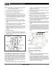
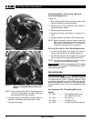
1. Place self-opening die head on bench in vertical po-
sition.
2. Make sure trigger assembly is released.
3. Loosen clamp lever approximately six full turns.
4. Pull lock screw out of slot under size bar so that roll
pin in lock screw will bypass slot. Position size bar so
that index line on lock screw is aligned with the end of
REMOVE DIES position.
5. Lay die head down with numbers up.
6. Remove dies from die head.
7. Insert new dies to mark on side of dies. Numbers 1
through 4 on the dies must match numbers on the die
head.
8. Move throwout lever back to lock in dies.
9. With head in vertical position, rotate cam plate until roll
pin on lock screw can be positioned in slot under size
bar. In this position dies will lock in die head. Make
sure roll pin points toward end of size bar marked RE-
MOVE DIES.
10. Adjust die head size bar until index line on lock screw
is aligned with proper size mark on size bar.
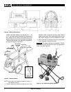
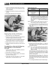
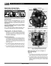
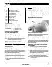
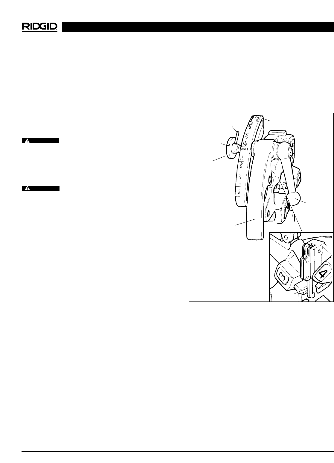
Figure 11 – Universal Self-Opening Die Head
11. Tighten clamp lever.
12. If oversize or undersize threads are required, set
the index line in direction of OVER or UNDER size
mark on size bar.
NOTE! When left hand threading the UNDER/OVER
positions are reversed.
Installing Dies In Quick-Opening Die
Head (Right and Left Hand)
The No. 811A Universal Die Head (Figure 11) for right
hand threads requires four sets of dies to thread pipe
ranging from
1
/
8
″ through 2″. One set of dies is required for
each of the following pipe size ranges: (
1
/
8
″), (
1
/
4
″ and
3
/
8
″), (
1
/
2
″ and
3
/
4
″) and (1″ through 2″). Bolt threading re-
quires a separate set of dies for each bolt size. No bolt
dies are available for left hand universal die heads.
1822-I Pipe and Bolt Threading Machine
WARNING
WARNING
Roll Pin
Index Line
Size Bar
Lock Screw
Throwout
Lever
Clamp
Lever
Trigger
Assembly