


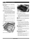
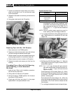
bracket is held in place by the axle shaft. Slide a
wheel onto the axle. Slide a flat washer over the axle
and install a cotter pin to hold the wheels on the axle.
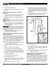
5. Mount machine to the stand using four (4) bolts that
mount into each corner of the base.
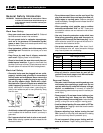
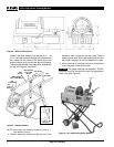
For proper balance and operation, RIDGID
machines must be mounted through the appropriate
holes in the rails (Figure 3).
Ridge Tool Company
6
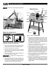
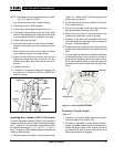
shown in the detail drawing. Use the four (4)
3
/
8
″ - 16
x 2
1
/
2
″ hex bolts to secure the legs to the cross-mem-
ber. Adjust the two halves of the stand stop to the
proper distance to fit into the rear legs on the stand.
The stand stop bracket is not required or supplied with
the No. 100 Leg and Tray Stand.
Figure 3 – Stand Assembly
NOTE! Insert axle into frame and secure it with a
1
/
2
″
lock washer and nut.
4. Position stand stop bracket so that the end of the
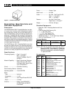
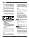
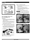
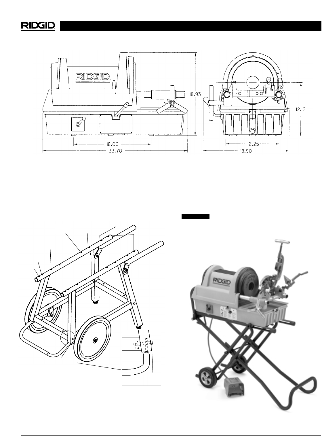
1822-I Pipe and Bolt Threading Machine
Figure 2 – Machine Dimensions
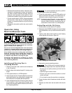
Figure 4 – No. 1406 Folding Wheel Stand
CAUTION
535
1224
(Rear)
1224
(Front)
535 (Front)
Detail Section
300 Compact
1233, 1822 (Rear)
300 Compact
1233, 1822
(Front)
3
/
8
″ - 16 x 2
1
/
2
″ Bolt
4 Required
535
Automatic
535
Automatic