


Ridge Tool Company
15
1822-I Pipe and Bolt Threading Machine
Operation Instructions
Using Geared Threaders
WARNING
Do not wear gloves or loose clothing when oper-
ating Threading Machine. Keep sleeves and jack-
ets buttoned. Do not reach across the machine or
geared threader.
Do not use this Threading Machine if the foot
switch is broken or missing. Always wear eye
protection to protect eyes from dirt and other for-
eign objects.
To prevent tipping, proper set-up of the Threading
Machine and Geared Threader is required. Follow
instructions carefully.
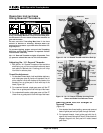
No. 141 Geared Threader weighs 95 pounds. Two
(2) persons should be used to lift this threader.
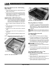
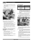
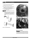
Adjusting No. 141 Geared Threader
1. With the No. 141 Geared Threader on floor and drive
shaft facing up, pull two cam plate knobs and rotate
cam plate to desired size. Locating pins will drop
into holes in selector plate.
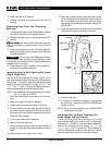
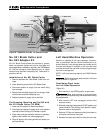
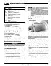
Thread Size Adjustment
1. For standard thread depth, hold workholder stationary
and rotate gear case by hand until standard line on
pinion sleeve is flush with bottom of die head or the
standard line on guide post is flush with top of die
head (Figure 18).
2. For oversized threads, rotate gear case until the 2T
Over Line on guide post is flush with top of die head.
3. For undersized threads, rotate gear case until the 2T
Under Line on guide post is flush with top of die head.
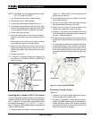
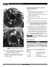
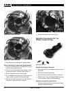
Indexing Guide Post For Straight Or
Tapered Threads
(Figure 19)
1. At a standard size thread setting, remove set screw at
base of guide post and pull post through die head.
2. For tapered threads, insert guide post with the di-
agonal slot inward through die head. Guide block will
engage diagonal slot and post will rotate toward
gear case.
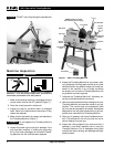
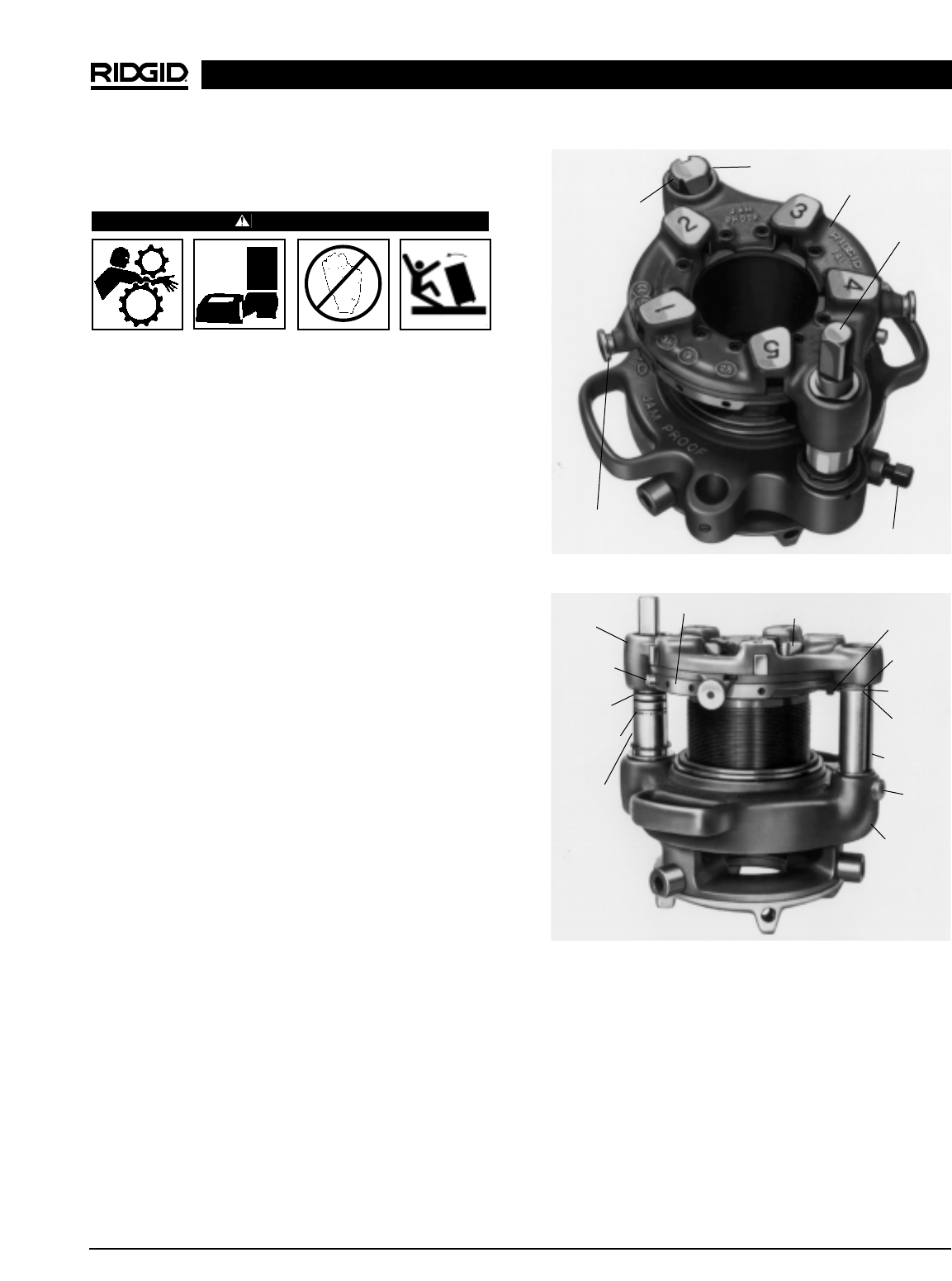
Figure 19 – No. 141 Geared Threader showing Pinion
Sleeve and Guide Post Reference Lines
Die (Set of 5)
Guide
Block
2T Under
Line
Standard
LIne
2T Over
Line
Screw
Guide Post
Gear Case
Selector
Plate
Die Head
Stop
Screw
Red Stop
Line
Standard
Line
Pinion
Sleeve
Guide Post
Head
Drive Shaft
Clamp Screw
Cam Plate
Knob (2)
Reference
Lines (3)
Figure 18 – No. 141 Geared Threader with Drive Shaft Up