


Ridge Tool Company
17
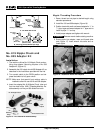
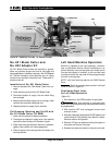
No. 821 Blade Cutter and
No. 822 Adapter Kit
No. 821 Blade Cutter allows the machine to groove,
bevel and produce square end cuts for lined pipe and
other applications. Installation requires a No. 822 Adapter
Kit. The kits includes a cutter attaching arm, oil supply
manifold and manifold clamp/drip tray. Reference in-
structions with kit.
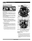
Installation of No. 821 Blade Cutter
1. Remove standard No. 364 Wheel Cutter from car-
riage.
2. Install attaching arm and No. 821 Blade Cutter.
3. Disconnect plastic oil supply line and metal fitting
from carriage.
4. Attach metal manifold supply line to carriage, install
manifold and manifold clamp/drip tray.
5. Reattach plastic oil supply line to manifold.
Cut Grooving, Beveling and Cut-Off with
No. 821 Blade Cutter (45 RPM)
1. Install tool bit required for desired operation.
2. Chuck pipe and place oil supply lever in the position
required to direct cutting oil to flexible oil spout.
3. Place cutter over pipe and with machine in operation,
tighten cutter handle until rolls engage pipe.
4. Direct oil spout to the cutting surface and slowly turn
tool feed handle.
Left Hand Machine Operation
Machine is capable of left hand operation. However,
user or Authorized Service Center modification is re-
quired. Basically, front and rear jaws are inverted and oil
lines are exchanged. In addition, a left hand die head
must be pinned to the near side of the carriage through
the hole in carriage rest.
NOTE! Left hand reaming requires an E-863 Reamer
Cone.
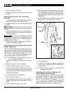
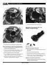
Both front and rear jaws must be in left hand
mode as shown in Figure 21.
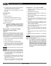
Positioning Front Jaws
for Left Hand Operation
(Figure 21)
1. Run machine in the OPEN position to open jaws.
Make sure machine is unplugged from
power source before performing maintenance or making
any adjustments.
2. With machine OFF and unplugged, remove front
and rear covers.
3. Manually rotate front jaws toward CLOSE position and
remove three E-Clips holding front retainer in place.
Remove retainer and spacers.
4. Remove E-Clips and washers holding front jaws on
drive pins and remove front jaws.
5. Reverse front jaws and install on drive pins and rods.
1822-I Pipe and Bolt Threading Machine
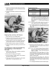
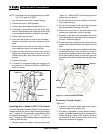
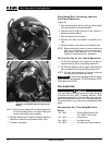
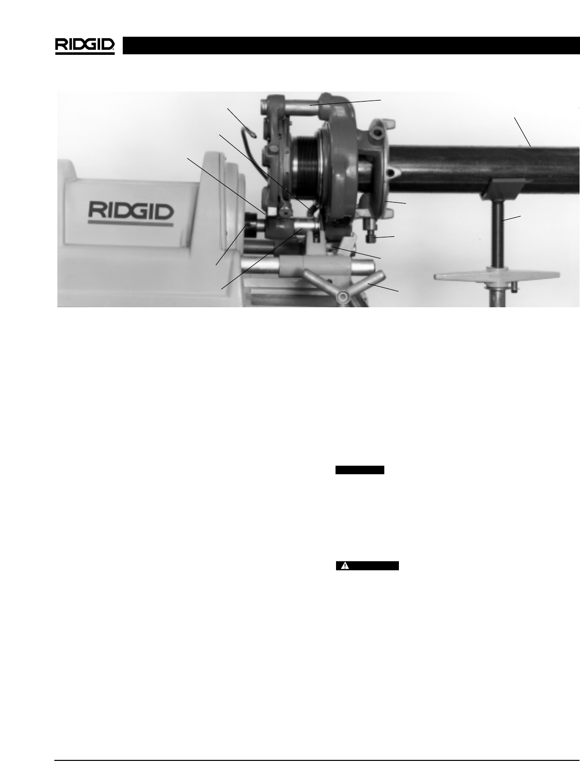
Figure 20 – Operation of the No. 141 Geared Threader
Oil Spout
Connecting
Link
Oil Manifold/Lever
(Hidden)
Drive Shaft
(Set Screws)
Guide Post
Workholder
Clamp Screw
Pipe
VJ-99 Pipe
Stand
Handwheel
Carriage
Saddle
Pinion Sleeve
CAUTION
WARNING