


28 C3662M (6/08)
XMUX2 INSTALLATION
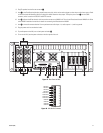
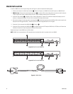
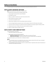
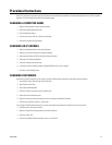
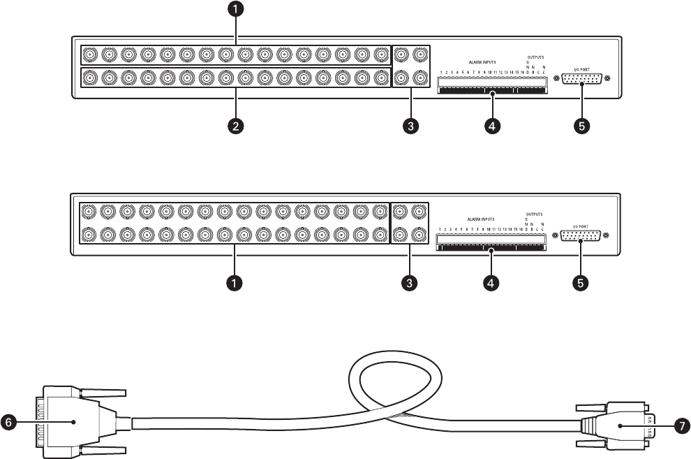
To install an XMUX2 unit, refer to Figure 29, Figure 30, and Figure 31, and then complete the following steps:
1. Connect your cameras to the video input connectors
ì. There are 16 inputs on an XMUX2-16 unit and 32 inputs on an XMUX2-32 unit.
2. XMUX2-16 only: Connect each camera loop-through output î to a monitor, VCR, or other analog device if you want to view live video on
a single, larger screen. Output 1 displays video from input 1, output 2 displays video from input 2, and so forth.
3. Connect the Aux connectors ï to monitors, VCRs, or other analog devices, if desired. The multicamera output (Aux1) displays up to 16
cameras, as configured in DSAdmin. The Aux 2–Aux 4 connectors are single-camera outputs.
4. Wire any alarm triggers into the input portion of the trigger block
ñ. Connect the signal ground to the GND pin. Wire an alarm signal to the
output portion of the trigger block (NO, C, and NC) so you can see when a designated alarm is set or tripped.
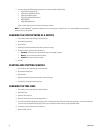
5. Connect the 15-pin connector of the XMUX Cable
s to Comm In ó.
6. Connect the 25-pin connector of the XMUX Cable r to the XPress board on the DS Enterprise SAVR, VAU, or DS XPress unit. Refer to the
installation instructions for those components to locate the XPress boards.
Repeat these steps for each XMUX2 unit and XPress board.
NOTE: XMUX2 units are powered by the DS component they are connected to; there is no power switch on an XMUX2.
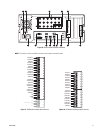
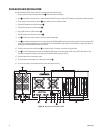
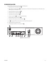
Figure 29. Rear Panel of XMUX2-16
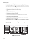
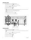
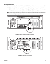
Figure 30. Rear Panel of XMUX2-32
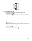
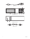
Figure 31. XMUX Cable