


C3662M (6/08) 23
XIO INSTALLATION
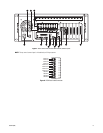
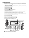
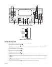
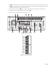
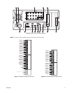
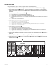
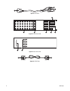
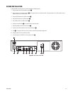
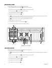
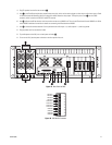
Refer to Figure 20; Figure 21, Figure 22, and Figure 23 on page 24; and then complete the following steps:
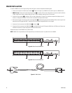
1. Plug the end of the XIO cable with three connectors
~ã into one of the video capture boards on the DS RealVue RAID system u.
2. Plug the other end of the XIO cable ~å into the XIO unit. The first video capture board on the DS RealVue RAID rear panel (from the left)
connects to the top connector on the back of the XIO unit
Ää. Each successive video capture board connects to the next available connector
on the XIO unit.
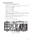
3. Connect your cameras to the BNC connectors on the XIO unit
~ç.
• On 8-input systems, you can use only the top row of connectors (inputs 1–8).
• On a 16-input system, you can use only the top two rows of connectors (inputs 1–16).
• On a 16-input system with looping outputs, the second and fourth rows are looping outputs for the corresponding inputs in the first and
third rows.
• On a 32-input system, you can use all 32 inputs.
4. Connect analog monitors, VCRs, and so forth to the analog outputs
~é.
• On 8-input systems, you can use only the top analog output.
• On a 16-input system, you can use only the top two analog outputs.
• On a 16-input system with looping outputs, only the top and third analog outputs are visible, and you can use both outputs.
• On a 32-input system, you can use all four outputs.
5. Connect audio devices to the audio inputs
~è.
• On 8-input systems, you can use only the top set of audio connectors.
• On a 16-input system, you can use only the top two sets of audio connectors.
• On a 16-input system with looping outputs, only the top and third set of audio connectors are visible, and you can use both sets.
• On a 32-input system, you can use all four sets of audio connectors.
6. Connect your alarm input devices to the alarm input connectors
Äí. Connect your alarms to the alarm output connector ~ë. Only Relay 1 is
currently used.
7. Wire optional RS-422–based PTZ cameras to the COM5 connector ~ê . Refer to PTZ Installation on page 29 for more details.
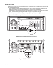
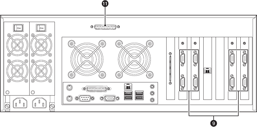
8. Connect one end of the DB-37 cable Äã to the 37-pin port on the XIO panel Äâ, and the other end of the cable Äå to the 37-pin port on the
DS RealVue RAID rear panel
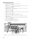
~â.
Figure 20. Rear Panel of DS RealVue RAID