


C3662M (6/08) 27
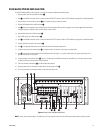
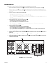
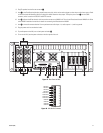
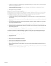
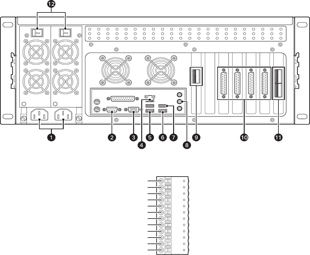
8. Plug PC speakers into the line out connector t.
9. Item u is the FlashGuard cardlet relay output (bottom two pins), which can be used to trigger an alarm when a critical error occurs. Refer
to FlashGuard and the WatchDog Service on page 40 for details about the relay output. The top four pins of item
u are the COM5
connector, which is used to wire RS-422–based PTZ cameras.
10. Item ~í indicates the XPress boards, which are used to connect to an XMUX2 unit. There is one XPress board for each XMUX2 unit. Refer
to the XMUX2 installation instructions for details on connecting the XPress boards to XMUX2.
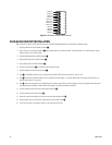
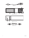
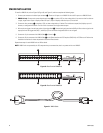
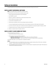
11. Item ~â is the audio connector bracket. From top to bottom are audio inputs 1–4, audio outputs 1–4, and four grounds.
12. Plug the power cord into an electrical outlet.
13. To provide power to the VAU, turn on both power switches
~ä.
14. To turn on the VAU, use the power switches on the front panel of the unit.
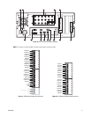
Figure 27. Rear Panel of VAU
Figure 28. VAU Audio Connector
GROUND 4
GROUND 3
GROUND 2
GROUND 1
AUDIO OUT 4
AUDIO OUT 3
AUDIO OUT 2
AUDIO OUT 1
AUDIO IN 4
AUDIO IN 3
AUDIO IN 2
AUDIO IN 1