


18 C3662M (6/08)
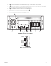
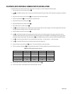
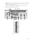
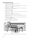
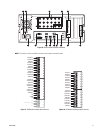
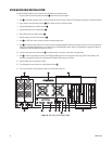
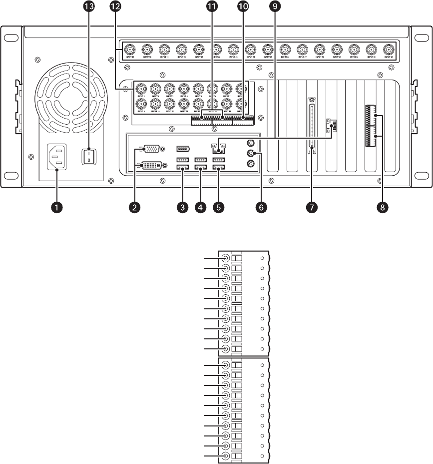
10. Item ~í is the COM5 connector, which is used to connect RS-422 PTZ cameras. Refer to PTZ Installation on page 29 for installation details.
11. Item ~â shows the connector for the 16 digital inputs and alarm output. Wire your alarm triggers into the input trigger block and connect
the signal ground to a GND pin. Wire an alarm device to AO+ and AO–.
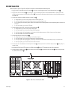
12. Connect cameras to the camera inputs=~ä. Inputs 17–32 (the top row of BNC connectors) are available only on 32-input systems.
13. Plug the power cord into an electrical outlet and turn on the power switch ~ã .
14. To turn on the server, use the power switch on the front panel of the unit.
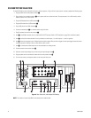
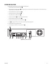
Figure 12. Rear Panel of DS 1000
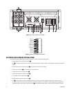
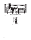
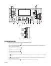
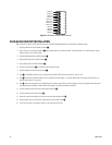
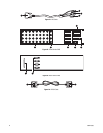
Figure 13. DS 1000 Audio Connector
GROUND 4
AUDIO IN 16
AUDIO IN 15
AUDIO IN 14
AUDIO IN 13
GROUND 3
AUDIO IN 12
AUDIO IN 11
AUDIO IN 10
AUDIO IN 9
GROUND 2
AUDIO IN 8
AUDIO IN 7
AUDIO IN 6
AUDIO IN 5
GROUND 1
AUDIO IN 4
AUDIO IN 3
AUDIO IN 2
AUDIO IN 1