


14 C3662M (6/08)
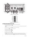
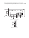
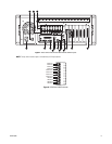
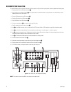
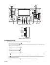
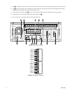
DS XPRESS (WITH INTERNAL CAMERA INPUTS) INSTALLATION
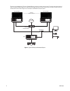
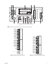
To install DS XPress with internal camera inputs, refer to Figure 7 on page 15, and then complete the following steps:
1. Plug the power cord into the power connector
ì.
2. Item î=is the COM1 connector, which is used to connect RS-232-based PTZ cameras. Refer to PTZ Installation on page 29 for installation
details.
3. Plug the monitor into the monitor connector
ï and its power cord into an electrical outlet.
4. Connect the network port
ñ to the network switch using Cat5 cable.
5. Plug the USB mouse into a USB connector ó.
6. Plug the USB keyboard into a USB connector r.
7. Plug a USB printer into a USB connector s.
8. Item t shows the connector for the 16 digital inputs and alarm output. Wire your alarm triggers into the input trigger block and connect
the signal ground to a GND pin. Wire an alarm device to AO+ and AO–.
9. Plug PC speakers into the line out connector u.
10. Item ~í is the FlashGuard cardlet relay output (bottom two pins), which can be used to trigger an alarm when a critical error occurs.
Connect the alarm to the bottom two pins of the 6-pin terminal block. Refer to the FlashGuard and the WatchDog Service on page 40 for
more details about the relay output. The top four pins in
u are the COM5 connector, which is used to wire RS-422–based PTZ cameras.
11. Item ~â is the audio connector bracket. From top to bottom are audio inputs 1–4, audio outputs 1–4, and four grounds.
12. Item ~ä is an optional SCSI card, which is used to connect to external storage units.
13. Connect cameras to the camera inputs ~ã. Inputs 17–32 are available only on 32-input systems.
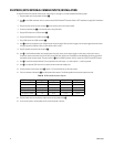
14. The four connectors indicated by ~å are multicamera video outputs. The following table shows how the outputs are used:
15. Plug the power cord into an electrical outlet and turn on the power switch
~ç.
16. To turn on the system, use the power switch on the front panel of the unit.
Table A. DS XPress Multicamera Outputs
DS XPress system Output 1 Output 2 Output 3 Output 4
16 inputs, 1 board 1–16 Unused Unused Unused
16 inputs, 2 boards 1–8 9–16 Unused Unused
16 inputs, 4 boards 1–4 5–8 9–12 13–16
32 inputs, 2 boards 1–16 17–32 Unused Unused
32 inputs, 4 boards 1–8 9–16 17–24 25–32