Parker Hannifin
Chapter 4 Communications 75
Depending on the communications protocol you are using, Aries can
automatically configure itself.
• If using RS-232, Aries will automatically detect and configure itself
for that communications protocol.
• If using RS-485 (two-wire) and the standard bias configuration,
Aries will automatically detect and configure itself for that
communications protocol.
For automatic detection to work, the RS-485 network must be
configured with an up bias on + (Talk) and a down bias on – (Talk).
RS-232 Communications
The Aries drive supports RS-232 communication. However, you cannot
connect the drive in an RS-232 daisy chain.
Pinout for RS-232 Communication
Pin Description
25 Rx (receive). Connect to Tx on your computer.
26 Tx (transmit). Connect to Rx on your computer.
24 DGND* (logic ground). Connect to DGND on your computer.
Maximum RS-232 cable length is 50 feet (15.25 meters).
* Many PC COM ports connect RS-232 ground to chassis ground.
Table 36 RS-232 Connector Pinout
RS-485 Communications
The Aries is designed to use RS-485 half-duplex (two-wire). In addition, you
can use it in multi-drop networks. For more information about multi-drop, see
“RS-485 Multi-Drop” on page 76.
Pinout for 2-wire RS-485 Communication
Pin Description
25 Connect to Tx/Rx+ on your computer.
26 Connect to Tx/Rx– on your computer.
24 DGND* (logic ground). Connect to DGND on your computer.
• Maximum RS-485 cable length is 1000 feet (305 meters).
• Keep wires as short as possible. Termination resistors may be required on long
cable runs.
• Connect RS-485 cables before applying power to the drive.
(Reconnecting the cables with power applied may cause the drive to interpret
intermittent connections as RS-232 hardware handshake signals; this may result
in shutdown of the RS-485 interface. If this happens, reset the drive to re-enable
the RS-485 interface.)
• Recommended cable: Belden 9842.
* Many PC COM ports connect RS-485 ground to chassis ground.
Table 37 RS-485 Connector Pinout
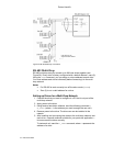
For connection information, see Figure 36.


