Parker Hannifin
Chapter 3 Electrical Installation 63
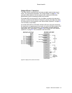
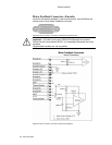
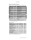
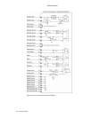
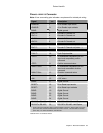
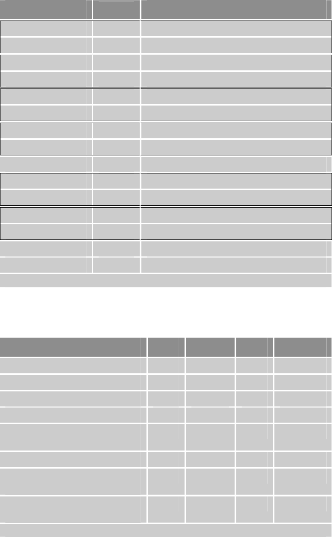
Pinout—MOTOR FEEDBACK Connector
Note: A box surrounding pins indicates a requirement for twisted pair wiring.
Signal
Pin
Description
ENC Z+ / Data+ 1 Encoder Z Channel in
ENC Z– / Data– 2 Encoder Z Channel in
DGND 3 Encoder power return
+5 VDC 4 +5 VDC Encoder power
+5 VDC 5 +5 VDC Hall power
DGND 6 Hall power return
ENC A– / SIN– 7 Encoder A Channel in
ENC A+ / SIN+ 8 Encoder A Channel in
Hall 1 / SCLK+ * 9 Hall 1 input
Thermal+ 10 Motor thermal switch/thermistor
Thermal– 15 Motor thermal switch/thermistor
ENC B / COS– 11 Encoder B Channel in
ENC B+ / COS+ 12 Encoder B Channel in
Hall 2 / SCLK– * 13 Hall 2 input
Hall 3 14 Hall 3 input
* When using the SinCos protocol, pins 9 and 13 require twisted pair wiring.
Table 24 MOTOR FEEDBACK Connector Pinout
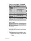
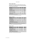
Inputs—Encoder
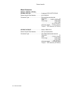
Description Min Typical Max Units
Common Mode Range -7 +7 V
Current—Encoder 250 mA
Current—Hall 250 mA
Differential Threshold Voltage -200 +200 mV
Differential Termination
Impedance
120 ohms
Thermal Switch Current 2 mA
Thermal Switch Voltage
Maximum (supplied)
15 V
Input Frequency
(pre-quadrature)
5 MHz
Note: All parameters are at the connector pin.
Table 25 Inputs—Encoder Inputs Electrical/Timing Characteristics


