


1-93
1. Specifications
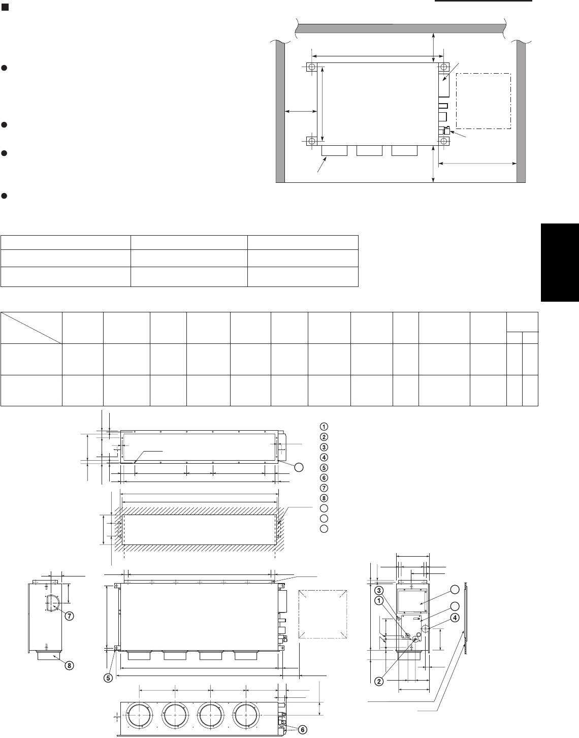
Low Silhouette Ducted Type (F1 Type)
6-22. Required Minimum Space for Installation and
Service
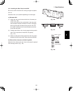
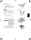
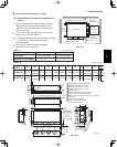
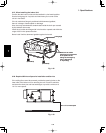
This air conditioner is usually installed above the
ceiling so that the indoor unit and ducts are not
visible. Only the air intake and air outlet ports are
visible from below.
The minimum space for installation and service is
shown in Fig. 1-67 and Table 1-7.
It is recommended that space be provided (17-23/32"
× 17-23/32") for checking and servicing the
electrical system.
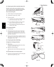
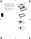
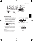
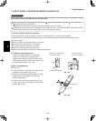
Fig. 1-68 and Table 1-8 show the detailed
dimensions of the indoor unit.
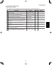
Table 1-7
Unit: inch (mm)
63 62 epyT
A (Length) 42-17/32 (1,080) 61-13/32 (1,560)
Number of duct flanges 4 3
A B C D E F G H I J K
35-7/16 9-21/32
S-26PF1U6
37-7/8
(7-3/32×5)
39-3/8 42-17/32 11-13/32 2-23/32 38-19/32 39-31/32 5-1/8
(9-21/32×1)
9-27/32 12 16
54-11/32 19-9/32
S-36PF1U6
56-25/32
(9-1/16×6)
58-9/32 61-13/32 13-3/16 12-7/32 57-15/32 58-27/32 5-1/8
(9-21/32×2)
9-7/16 16 18
No. of
holes
Dimension
Table 1-8
Unit: inch (mm)
Refrigerant tubing joint (liquid tube)
Refrigerant tubing joint (gas tube)
Upper drain port (O.D. 1-1/4 in.)
Bottom drain port (O.D. 1-1/32 in.)
Suspension lug
Power supply outlet (2-ø1-3/16 hole)
Fresh air intake port (ø5-29/32 hole)
Flange for the flexible air outlet duct (ø7-7/8 hole)
Tube cover
Electrical component box
Flange for the air intake duct
(Option or field supply)
9
10
9
10
11
11
(Suspension bolt pitch)
)
hc
t
ip
t
lo
b
n
o
i
sne
psuS
(
M-ø1/8
(Hole)
4-ø15/32
(Hole)
(Hole)
A (O.D.)
L-ø1/4
I
13/32
13/32
2
3
/3
1
23/5-28/
7
-
7
23/
5
-2
23/31
IJJK
B
C
)23/92-5(D
1-9/16
E E E F 2-15/16
2-9/16
11-7/32
2-3/4
5-1/8
31/32 8-9/32
12-7/32
31/32
6-7/8
1-3/8
3-17/32
1-7/321-7/32
H (Duct suspension bolt pitch)
G (Ceiling opening dimension)
23
/1
3
6
1/5
1
-
3
23
/
9
-
7
23
/7
2
-
222
3
/
13
23
/
71
-4
2
3
/
5
1
-
7
23/11
-
3
2
3
/
13
6
1/
3-
14
/
3-2
6
1
/
5-6
2
3/
1
3
6
1/
3
1-
42
23
/
31
23/51
-
3
6
1/3
1
-
0
1
)n
o
i
sn
e
mid
g
n
in
epogni
l
i
eC
(
4
/1-01
).D.O(
3/43/4
Inspection access
(17-23/32
×
17-23/32)
(Field supply)
Inspection access panel
Ceiling
Indoor Unit
Inspection
access
17-23/32
×
17-23/32
Air outlet duct flange
min.
9-27/32
.nim
4/3
-
51
min. 25-19/32
23/72-22
A (Suspension bolt pitch)
Electrical
component box
Refrigerant
tubing
Unit: inch
.nim
2
3
/72-
9
Fig. 1-67
Fig. 1-68
L
M
Unit: inch
Type
1