


1-108
1. Specifications
7-13. Electrical Wiring
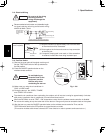
CAUTION
Be sure to do the wiring
correctly (incorrect
wiring will damage the
equipment).
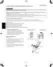
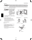
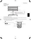
Recommended wire diameter and allowable length
for signal receiving unit wiring and its branch wiring:
AWG #18, MAX 1,300 ft.
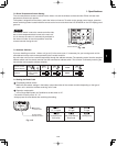
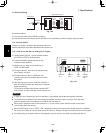
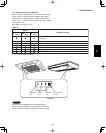
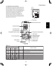
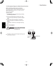
7-14. Test Run Switch
(1) Remove the cover plate of the signal receiving unit.
Set the “TEST RUN” switch of the dip switches to
the ON position.
(2) Press the ON/OFF operation button on the
wireless remote controller.
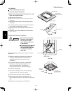
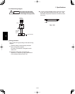
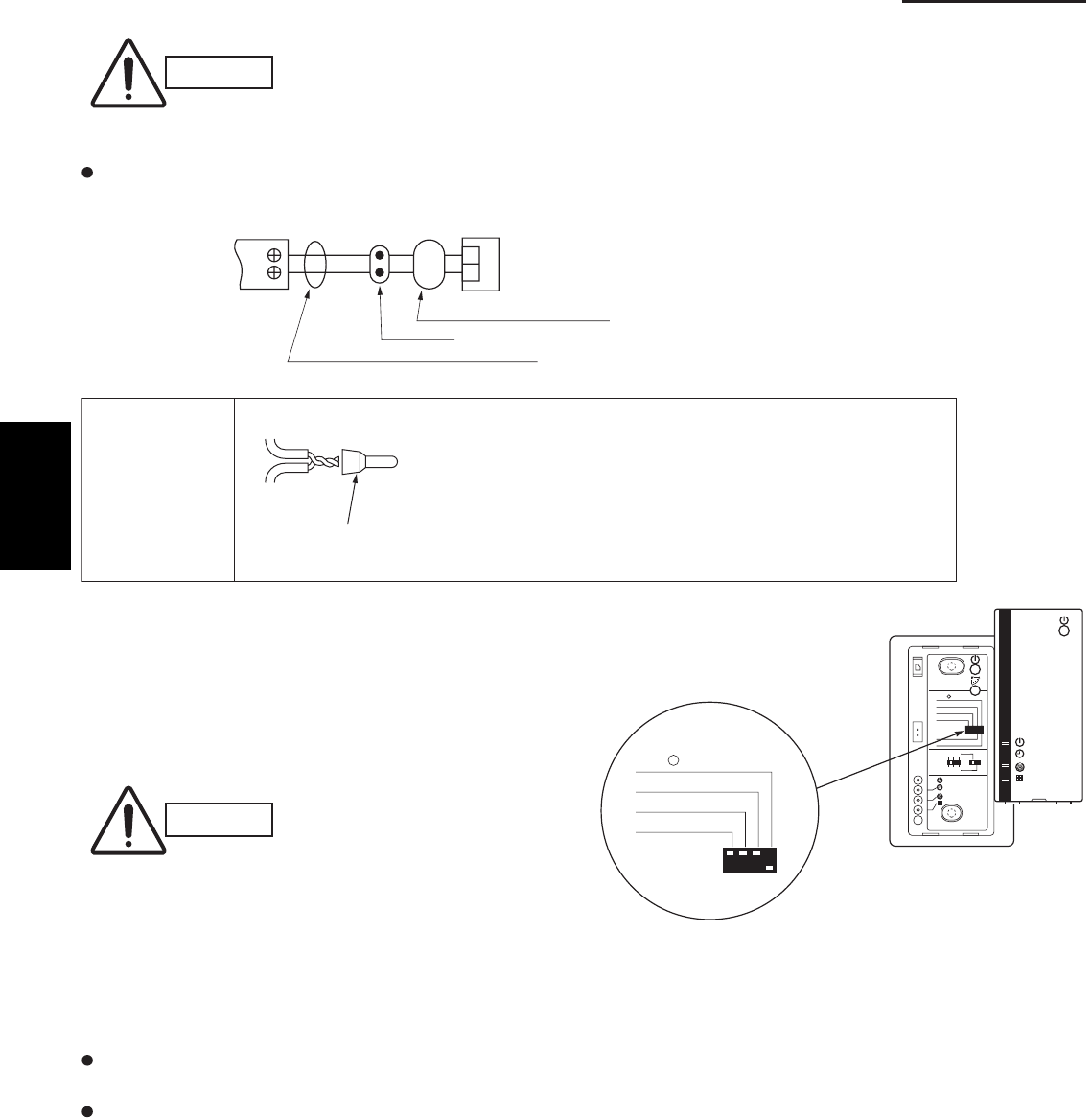
Wire joint (2 pcs.
white, supplied)
1
WHT
BLK
2
1
2
Terminal board
for indoor unit
remote control
wiring
Signal receiving unit wiring (field supply)
Connection
Wire from signal receiving unit
Signal receiving
unit
Wire joint CE-1
(supplied)
Signal receiving
unit wiring
Signal receiving
unit wiring
CAUTION
To avoid placing an
excessive load on the
equipment, use this
function only when
conducting the test run.
(3) Make a test run using the air conditioner in
COOL or HEAT mode.
(4) During the test run, the “OPER.,” “TIMER,”
and “STDBY” LED all blink.
To protect the air conditioner from overloading, the outdoor unit will not start running for approximately 3 minutes
after power is applied or the air conditioner is turned off and then back on.
When the DIP switch is set to “TEST – ON,” temperature control from the wireless remote controller is disabled.
Do not use this setting at any time other than for the test run. Doing so will place an excessive load on the system.
(5) After the test run, press the ON/OFF operation button on the wireless remote controller. Then, set the
TEST RUN switch back to the OFF position to cancel the test run mode.
(This receiver includes a 60-minute automatic OFF timer function in order to prevent continuous test run.)
Fig. 1-106
123
4
ADR
56
ALL•
RCU : SUB
RCU : MAIN
NORMAL
PCB CHK.
TEST RUN
ALL•
RCU : SUB
PCB CHK.
TEST RUN
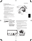
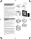
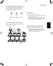
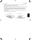
(1) Strip the insulation to approximately 9/16" from the ends
of the wires that will be connected.
(2) Twist together the 2 wires and create a crimp connection
at the wire joint.
(3) If a special crimping tool is not used, or if the connection
is soldered, insulate the wires using insulation tape.
1