


1-107
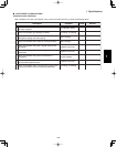
1. Specifications
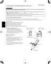
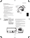
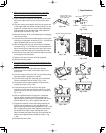
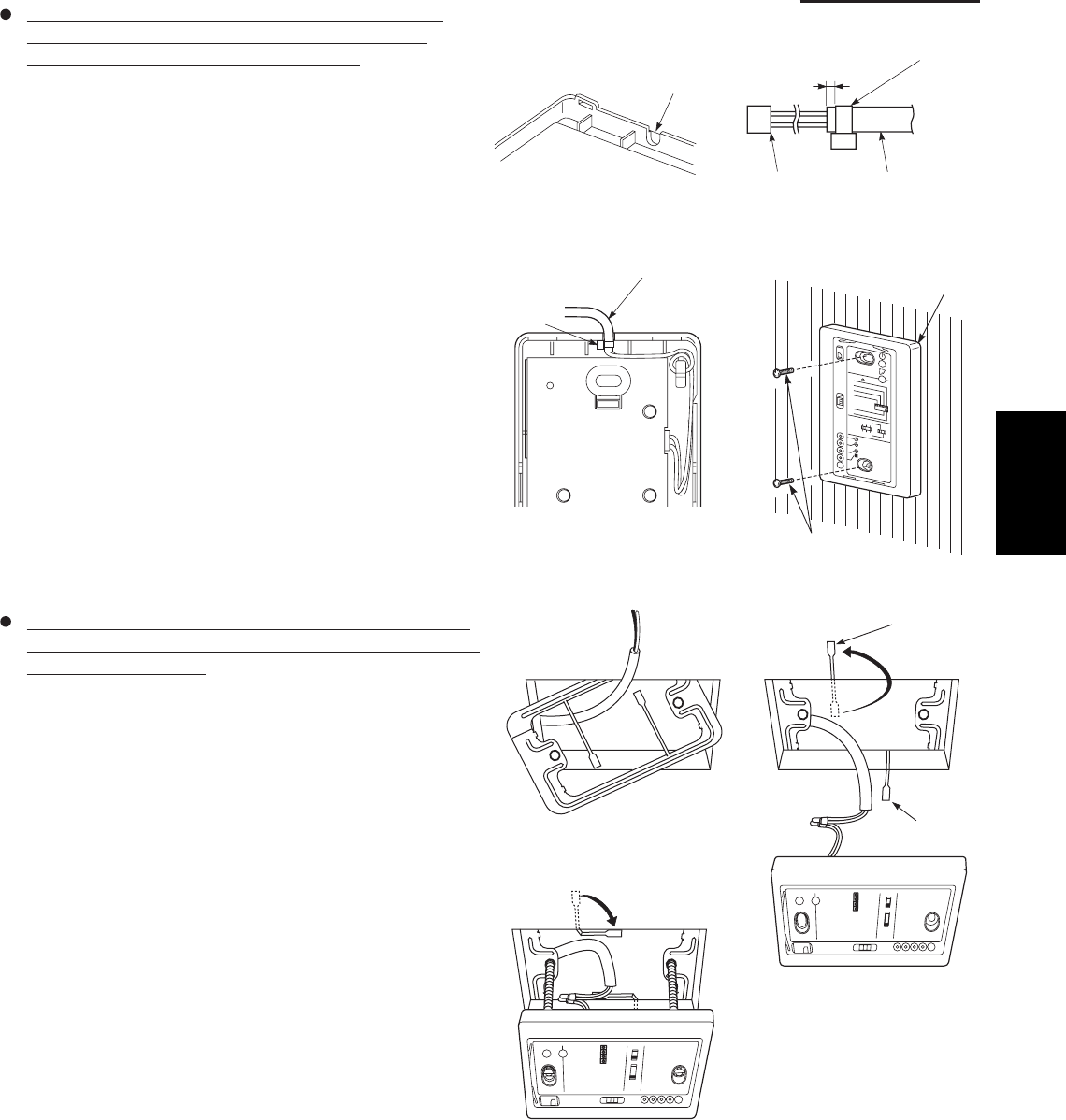
When using the signal receiving unit on a wall with
the front exposed, choose a wall surface that the
signal receiving unit can be mounted on.
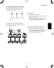
(1) Insert a fl athead screwdriver into the slot on the lower
side of the signal receiving unit and pry off the back
case.
(2) The wire routing at the signal receiving unit comes out
of the upper case (thin portion at upper center) so use
nippers or a similar tool to cut out a notch beforehand
large enough for the remote control cable (option) to
pass through as shown in Fig. 1-99.
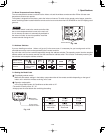
(3) Remove the wire, which is connected prior to shipping,
from the connector.
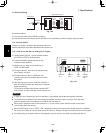
(4) Connect the remote control cable (option) to the signal
receiving unit connector as shown in Fig. 1-100 after the
clamp (supplied) with the unit is installed.
(5) After arranging the wiring on the printed circuit board
as shown in Fig. 1-101 so that it is contained within the
signal receiving unit, attach the back case. At this time,
arrange so that the head of the clamp faces the side.
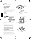
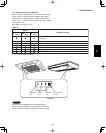
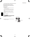
(6) Remove the cover plate and install the signal receiving
unit using the 2 wood screws.
(7) Fasten to the wall using the cord clip (supplied).
(8) Reinstall the cover plate.
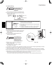
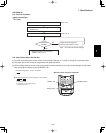
To use the signal receiving unit while mounted on the
ceiling, install by using the carrier for ceiling installation
supplied with the unit.
(1) Remove the cover plate by inserting a fl athead
screwdriver into the notch in the lower section and
prying it off.
(2) Cut out a section (3-3/4"×2-1/32") on the ceiling using
the paper pattern (supplied) as a guide.
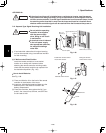
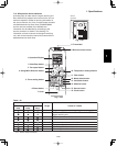
(3) Run the wire through the mounting carrier and insert
into the installation hole as shown in Fig. 1-103.
(4) Fit securely into the ceiling material at sections (A)
and (B) as shown in Fig. 1-104.
(5) Connect the wire (2-wire core) from the signal
receiving unit with the wire from the indoor unit. (See
section on how to wire the receiving unit.) as shown in
Fig. 1-104.
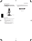
(6) Use the supplied spacers to adjust for a thickness
several inches more than the ceiling material and
lightly fasten the receiving unit in place with the small
screws (M4×1-9/16", 2 pcs.) supplied with the unit.
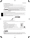
(7) Tighten the machine screws after fi tting sections (A)
and (B) into the openings, in the gap between the
signal receiving unit and ceiling surface as in Fig. 1-105.
Do not apply strong force when tightening the screws.
Excessive force might warp or damage the cover.
When fi nished, the signal receiving unit should still be
able to move slightly when pressed as shown in Fig.
1-105.
(8) Reinstall the cover plate.
Run the remote con
cable through a notch
in the upper case.
Clamp (Supplied)
About 3/32"-1/8"
Connector
Remote control cord
(Option)
Remote control cord (Option)
Clamp
Signal receiving unit
Wood screws (2)
123
4
R
D
A
6
5
•L
L
A
BU
S
:
U
C
R
N
I
AM
:
U
C
R
L
A
M
RO
N
.
K
H
C
B
C
P
NU
R
T
S
E
T
B
A
Fig. 1-99
Fig. 1-100
Fig. 1-101
Fig. 1-102
Fig. 1-103
Fig. 1-104
Fig. 1-105
1