


4-5
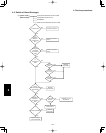
4. Service procedures
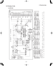
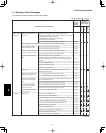
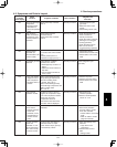
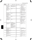
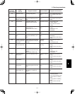
4-2. Symptoms and Parts to Inspect
Judgment condition
Clear condition
P03
P05
P04
P15
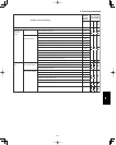
P19
P20
P22
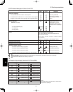
P26
Remote
controller
alarm display
Alarm
contents
Judgment and
correction
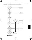
Abnormal discharge
temperature
• Discharge temp.
detected at or
above the specified
value.
Stops when temp. exceeds
232 ˚F.
Recovery at restart
Recovery at restart
Recovery at restart
Recovery at restart
Recovery at restart
Recovery at restart
Recovery at restart
Recovery at restart
1. Check refrigerant cycle
(gas leak).
2. Electronic control valve
trouble
3. Check tubing sensor (TD).
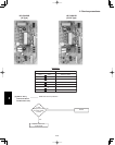
Missing phase
High pressure
switch is activated.
Compressor motor
thermal protector is
activated.
detected. (CT
disconnected or AC
power trouble)
Current value sent from MDC
Stops when pressure
exceeds 600 psi.
Stops when temp. exceeds
230 ˚F.
on outdoor unit control PCB is
low.
No AC power input for 3
minutes or longer: pre-trip - 5
1. Check R/S/T power.
2. Check inverter control PCB.
3. Check outdoor unit control
PCB.
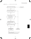
Insufficient gas level
detected.
The following conditions
continue for 1 minute.
• Discharge temp. is 203 ˚F or
higher.
• Electronic control valve is at
step 480.
• Current value from MDC is
2.0 A or less.
Check refrigerant cycle
(gas leak).
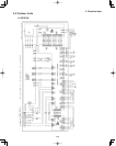
4-way valve locked
• Judgment occurs
after compressor
has been ON for 5
minutes.
Indoor heat exchanger temp.
drops although compressors
are ON in heating mode:
[min(E1, E2)] ≤ 50 ˚F.
Indoor heat exchanger temp.
rises although compressors are
ON in cooling mode:
E2 ≥ 104 ˚F.
1. Check 4-way valve.
2. Check 4-way valve wiring.
3. Check outdoor unit control
PCB.
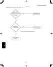
High-pressure
protection trouble
1. Refrigerant cycle
overload operation
2. Outdoor coil temperature
sensor C1 or C2
Outdoor unit fan
motor trouble
• Inverter protection
circuit was
activated, or lock
was detected, at
outdoor unit fan
motor.
Inverter stops after alarm is
detected
1. Position detection trouble
2. Overcurrent protection
circuit at outdoor unit fan
motor was activated.
• Check outdoor unit control
PCB.
• Refer to outdoor unit fan
judgment methods.
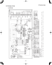
Inverter protection
circuit was
activated, or G-Tr
short-circuit (short
time: 0.8 s or less)
in inverter control
Inverter stops after alarm is
detected. Alarm is output
when inverter stops (pre-trip)
consecutively 4 times.
1. Stops immediately when
restarted.
• Layer short in the
compressor
2. Check inverter control
PCB.
• Wiring trouble
1. Check the high pressure
switch connector is
securely connected.
2. Check the ourdoor unit heat
exchanger is not clogged
(cooling operation).
3. Check the indoor unit air
filter has not become
clogged (heating operation)
If MAX (C1,C2) is 142°F or
higher, the compressor stops
one. The compressor restarts
three time, and if the
temperature does not
decrease to less than 142°F,
the alert “P20” is displayed.
4