


2-4
2. Processes and functions
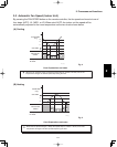
Fig. 3
92
88
81
77
50
SET
FAN
SPEED
AUTO OR H
M
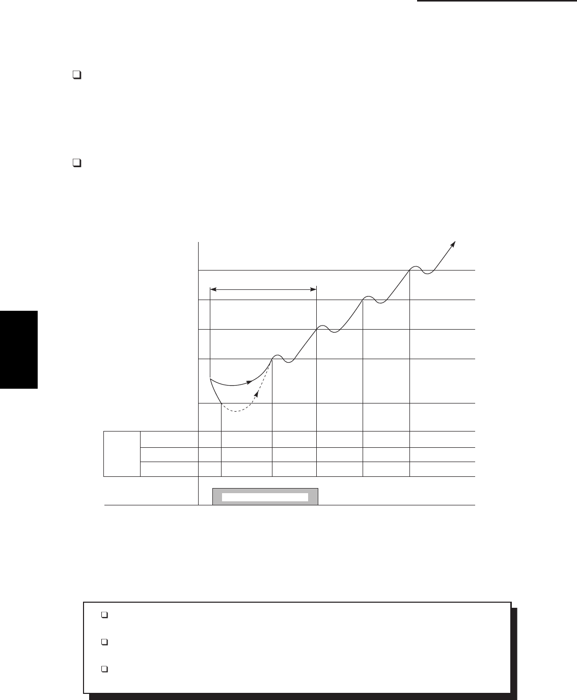
L LL LL/OFF LL L L L
LL LL/OFF LL L M M
LL LL/OFF LL L M H
MAX. 6 MINUTES
“STANDBY”
INDICATOR
INDOOR UNIT
COIL TEMP.
E2 (°F)
LL= Very low speed
L= Low speed
M= Medium speed
H= High speed
“STANDBY” APPEARS
1135_THS_I
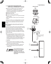
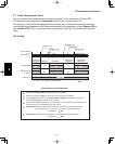
Chart Summary and Explanations
The main idea of this chart is to show that the indoor fan speed increases and gets closer to
the set fan speed as the coil temperature E2 rises.
The indoor unit fs coil temperature is taken from sensor E2 located in the middle of the indoor
heat exchange coil.
The dotted line shows that the indoor fan motor is OFF. When the temperature at sensor E2
falls below 50 ˚F, the indoor fan motor stops running.
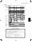
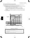
2-2 Cold Draft Prevention (Heating Cycle)
The cold draft prevention function controls indoor fan speed so a strong draft of cold air will
not blow out before the indoor heat exchange coils have warmed up.
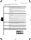
STANDBY shows on the remote controller when the indoor fan speed is LL (very low)
or OFF. This condition occurs in the following 3 cases:
• During Thermo OFF (refer to 2-1 B. Room Temperature Control, Heating)
• During the defrosting operation (refer to 2-10 Defrosting Control, Heating)
• Until either the coil temperature E2 reaches 81°F or when a maximum of 6 minutes
has past.
The indoor fan motor operates in L instead of LL for 3 seconds as it starts to give the
fan an initial boost.
2