


6-8
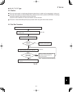
6. Test run
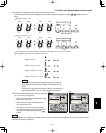
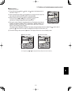
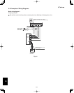
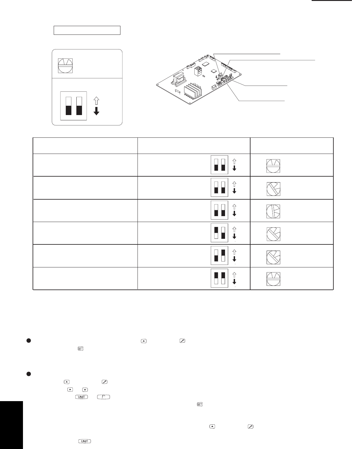
Setting the outdoor unit system addresses
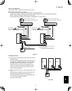
For basic wiring diagram 2 (Set the system addresses: 1, 2, 3...)
ON
1
2
0
System address rotary switch
(Set to “0” at time of shipment)
System address rotary switch
System address
DIPswitch
OFF
ON
10s 20s
3 – 5HP
Outdoorunit control PCB
Fig. 6-7
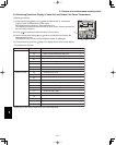
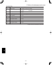
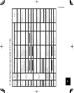
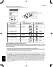
System address No.
System address 10s digit
(2P DIP switch)
System address 1s place
(Rotary switch)
0 Automatic address
(Setting at shipment = “0”)
1 (If outdoor unit is No. 1)
“0” setting
0
0
1
1
1
2
Both OFF
Both OFF
Both OFF
10s digit ON
20s digit ON
10s digit and 20s digit ON
“1” setting
“2” setting
“1” setting
“1” setting
“0” setting
2 (If outdoor unit is No. 2)
11 (If outdoor unit is No. 11)
21 (If outdoor unit is No. 21)
30 (If outdoor unit is No. 30)
ON
ON
OFF
12
ON
ON
OFF
12
ON
ON
OFF
12
ON
ON
OFF
12
ON
ON
OFF
12
ON
ON
OFF
12
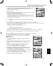
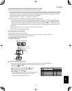
Automatic address setting using the remote controller
When the outdoor unit shown in “Basic wiring diagram 2” is used for group control of multiple outdoor units , use the
remote controller to perform automatic address setting. (During automatic address setting, “SETTING” blinks on the
remote controller display.)
Press the remote controller timer time button and
button simultaneously. (Hold for 4 seconds or longer.)
Then press the button. (Item code “AA” appears: All systems automatic address setting.)
(Automatic address setting is performed in sequence for all outdoor units from No. 1 to No. 30. When automatic
address setting is completed, the units return to normal stopped status.)
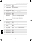
To select each refrigerant system individually and perform automatic address setting, press the remote controller
timer time button and
button simultaneously. (Hold for 4 seconds or longer.) Then press either the tempera-
ture setting or button. (Item code “A1” appears: Individual system automatic address setting)
Use either the
or
button to select the outdoor unit to perform automatic address setting. (For example,
when selected R.C.1 “R.C.1” is displayed.) Then press the button. (Automatic address setting is performed for
refrigerant circuit 1.) When automatic address setting for circuit 1 is completed, the system returns to normal
stopped status. When automatic address setting for circuit 1 is completed, the system returns to normal stopped
status. In the same way, press the remote controller timer time button and button simultaneously to per-
form automatic address setting for a different R.C. (refrigerant circuit) if necessary. Then in the same way as
above (use the button to display “R.C.2,” for example), select the next circuit and perform automatic ad-
dress setting.
System address rotary switch
System address 10s digit and 20s digit
DIP switch
Automatic address
button (black)
Terminal plug (black)
6