


1-103
1. Specifications
Ceiling Type (T1 Type)
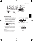
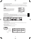
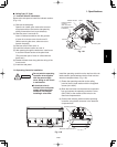
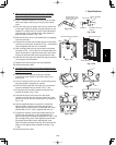
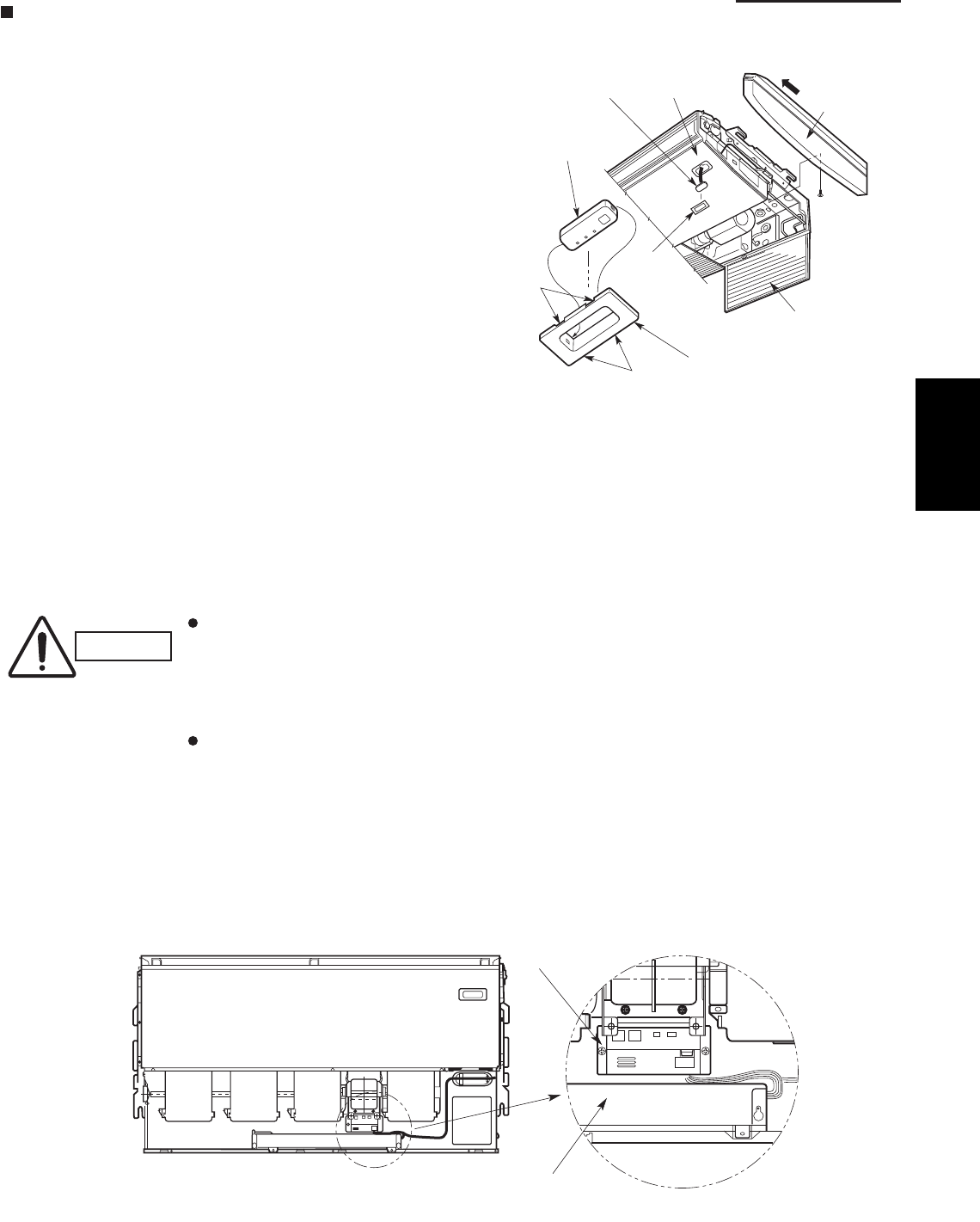
7-7. Indicator Section Installation
Remove the side panel to install the indicator section.
(Fig. 1-91)
(1) Remove the side panel.
Open the air intake grille, remove the screw at
one place and then remove the side panel by
sliding it toward the front (arrow direction).
(2) Remove cover A and cover B.
Insert a fl athead screwdriver into the grooves
of cover A to remove cover A and cover B.
(When removing the cover, take care not to
scratch the panel.)
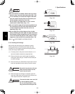
(3) Remove cover B from cover A.
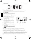
(4) Install the indicator section at cover A.
(5) After passing through the lead wires, install cover
A and the indicator section at the panel hole.
(The protrusion part of cover A is fi xed with the
panel hole.)
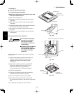
(6) Bundle the lead wires along with the wiring of the
louver motor.
(7) Install the side panel.
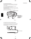
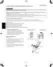
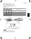
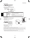
7-8. Operating Controller Installation
Install the operating controller on the top face of the air
intake section (space between the fan motor and the
electrical component box). (Fig. 1-92)
(1) Fasten the operating controller to the ceiling
panel of the air intake section with the 2 supplied
screws (4×L13/32").
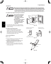
(2) Draw the lead wires into the electrical component
box and connect the operating controller 2 wires
(WHT, BLK) to the remote control wires in the
electrical component box.
(3) Connect the indicator section and the operating
controller using the 6P connector in the electrical
component box.
CAUTION
Do not twist the operating
controller wires together
with the power supply
wires. Doing so can result
in malfunction.
If electrical noise is
induced in the unit power
supply, take appropriate
measures, for example
installing a noise filter.
Fig. 1-91
Fig. 1-92
Cover A
Cover A
PanelIndicator section
Side panel
Indicator section
Cover B
(Not used when
the indicator section
is installed.)
Air intake grille
Grooves
Grooves
Operating controller
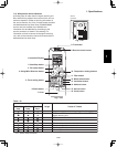
Electrical component box
1