


6-5
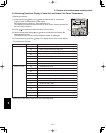
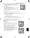
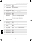
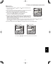
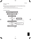
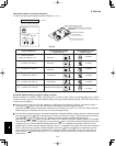
6. Test run
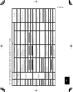
Wired remote
controller display
Cause
Correction
Nothing
is
displayed
Nothing is
displayed
E 0 1
dis
played
E 0 2
displayed
E 0 9
displayed
E 1 4
displayed
E 0 4
displayed
E 0 6
di
splayed
E 1 5
displayed
E 1 6
displayed
E 2 0
di
splayed
P 0 5
displayed
L 0 2
displayed
L 1 3
displayed
P 0 9
displayed
L 0 7
displayed
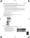
Indoor unit
receiver lamp
Operating
lamp
is blinking.
Standby lamp
is
blinking.
Both the Operation
lamp and S
tan
dby
lamp are blinking
together.
Operation lamp an
d
S
tan
dby lamp are
blinking alternately.
Timer lamp and
S
tan
dby lamp are
blinking alternately.
Remote co
ntroller is not connected correctly.
Indoor un
it power i
s not ON.
A
utomatic address setti
ng has n
ot been
completed.
Inter-unit control wiring is cut or is not
connected correctly.
Remote controller is n
ot conn
ected correctly
(remote controller receiving failure).
Remote co
ntroller is not connected correctly
(failure in transmission from remote controller
to indoor unit).
Indoor-outdoor inter-unit wiring is not
connected correctly.
Indoor unit capacity is too low.
Indoor un
it capacity i
s too hi
g
h.
No s
erial sign
al is
bei
ng received at all from
the indoor units.
Inter-unit circu
it or ope
n phase i
n
the o
u
tdoor
unit power
Insufficie
nt
g
as
Indoor-outdoor unit type mismatch
The indoor unit ceiling panel connector is not
conn
ected correctly.
Remote controller is not connected with
indoor unit correctly
Indoor unit power is not ON.
Automatic address setting has not been
completed.
Inter-unit control wiring is cut or is not
connected correctly.
Remote controller is not connected with
indoor unit correctly
Remote controller is not connected with
indoor unit correctly
Same as at left
I
ndoor-outdoor inter-un
it wiring is cut or
is not connected correctly.
Same as at left
Reversed phase or open phase in the
3
-phase power at one of the outdoor
un
its
i
n the
group
Same as at left
Same as at left Same as at left
Same as at left
Same as at left
Same as at left
Same as at left
Same as at left
Same as at left
Same as at left
Same a
s at left
Same as at left
Same as
at left
S
ame as at left
Same as at left
Same as at left
Same as at left
Same a
s
at left
Remote controller crossover wiring is cut or
is not connected correctly.
Indoor unit ceiling panel connector is not
connected correctly.
Remote controller crossover wiring is co
nn
ected
to the indoor unit, however it is set for individual
operation.
Connect the remote controller correctly.
Turn ON the indoor unit power.
2 remote controllers are
set as the main remote
controller.
Check the remote controller and inter-unit
control wiring.
Perform automatic address setting.
Connect the remote controller correctly.
Refer to 11-8-6 Main-sub remote control, and
make the correct settings.
Check the remote controller crossover wiring.
Perform automatic address setting again.
Connect the wiring correctly.
Refer to 11-8 System Control, and make the
correct settings.
Check that the total capacitie
s
of the i
n
door
and outdoor un
it
s are appropriate.
Check that the indoor unit power is ON, and that
the inter-unit control wiring is connected correctly.
Reverse 2 phases of the outdoor unit 3-phase
power and connect them correctly.
Check that the indoor and o
u
tdoor unit types
are correct.
Perform automatic address s
etti
ng.
Connect the indoor unit ceiling panel
co
nn
ector correctly.
Ceiling panel connector at one of the
indoor
unit
s in the g
ro
u
p i
snot
connected correctly.
Reversed phase or ope
n
phase in the
outdoor unit 3-phase power
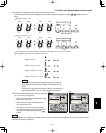
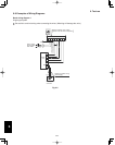
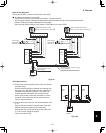
1:1 connectio
nognis(
rG)e
pytenoitcennoc pul
Simultaneous-operation multi system
(flexible combination)
Control by main-sub
remote controllers
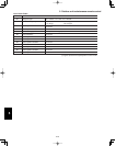
6-7. Table of Self-Diagnostic Functions and Corrections (X, T, U, K Type)
6-7. Table of Self-Diagnostic Functions and Corrections (U1, K1, T1, F1 Type)
6