


1-61
1. Specifications
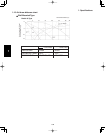
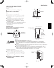
Inter-unit
power wiring
Power wiringInter-unit
control wiring
8P terminal board
Outdoor Unit
Indoor Unit
U1 U2 1 2 G L1 L2
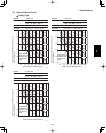
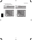
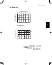
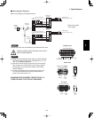
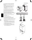
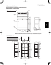
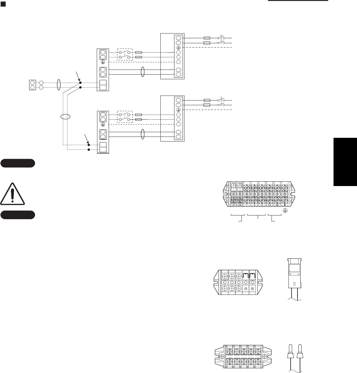
Wiring System Diagrams
Basic wiring diagram for standard control
NOTE
Disconnect switch may be needed by the National/Local code.
ALWAYS COMPLY WITH NATIONAL AND LOCAL
CODE REQUIREMENTS.
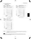
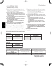
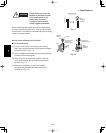
NOTE
(1)
(2)
(B), (C) have no polarity. But for other wiring, respect
polarity. Be sure to connect as shown in the Wiring
System Diagram.
(3)
Refer to Recommended Wire Length and Wire Diameter
for Power Supply System for the explanation of “A”, “B”
and “C” in the above diagrams.
Inter-Unit Control Wiring (A) and remote control wiring
In case of separate supply connection to indoor unit,
over current protection must be provided between
power source and indoor unit.
MAXIMUM OVER CURRENT PROTECTION 15 A
(FUSE OR HACR TYPE CIRCUIT BREAKER)
U2
L2
U1
L1
L1
L2
U1
U2
L2
L1
2
1
WHT
Remote
Controller
B
C
Indoor
unit
L1
L2
Grounding line
BLK
2
1
Inter-unit power line
208 / 230 V, 60 Hz
, 1-PH
Power supply
208 / 230 V, 60Hz, 1-PH
Grounding line
A
Outdoor unit
INV unit
1
2
G
*
U2
U1
L1
L2
U1
U2
Indoor
unit
L1
L2
Grounding line
Inter-unit power line
208 / 230 V, 60 Hz
, 1-PH
Power supply
208 / 230 V, 60Hz, 1-PH
Grounding line
A
Outdoor unit
INV unit
1
2
G
*
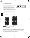
* Disconnect switch
Field supply
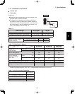
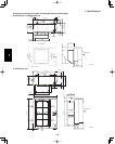
Wire joint
connection
Wire joint
connection
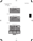
Unit
control
Line
Power
supply
Remote
control
Line
5P terminal board
L1 L2
U1 U2
K1 Type
L1 L2
Unit
control
Line
U1
Power
supply
U2
5P terminal board
U1, T1, F1 Types
Remote
control
Line
1