


1-87
1. Specifications
6-15. Wiring Instructions
General Precautions on Wiring
(1) Before wiring, confirm the rated voltage of the unit as shown on its nameplate, then carry out the wiring closely
following the wiring diagram.
(2) Provide a power outlet to be used exclusively for each unit. A power supply disconnect and circuit breaker for
overcurrent protection should be provided in the exclusive line.
(3) To prevent possible hazards from insulation failure, the unit must be grounded.
(4) All wiring must be connected tightly.
(5) Do not allow wiring to touch refrigerant tubing, compressor, or any moving parts of the fan.
Unauthorized changes in the internal wiring can be very dangerous. The manufacturer will
accept no responsibility for any damage or misoperation that occurs as a result of such
unauthorized changes.
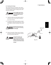
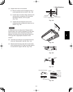
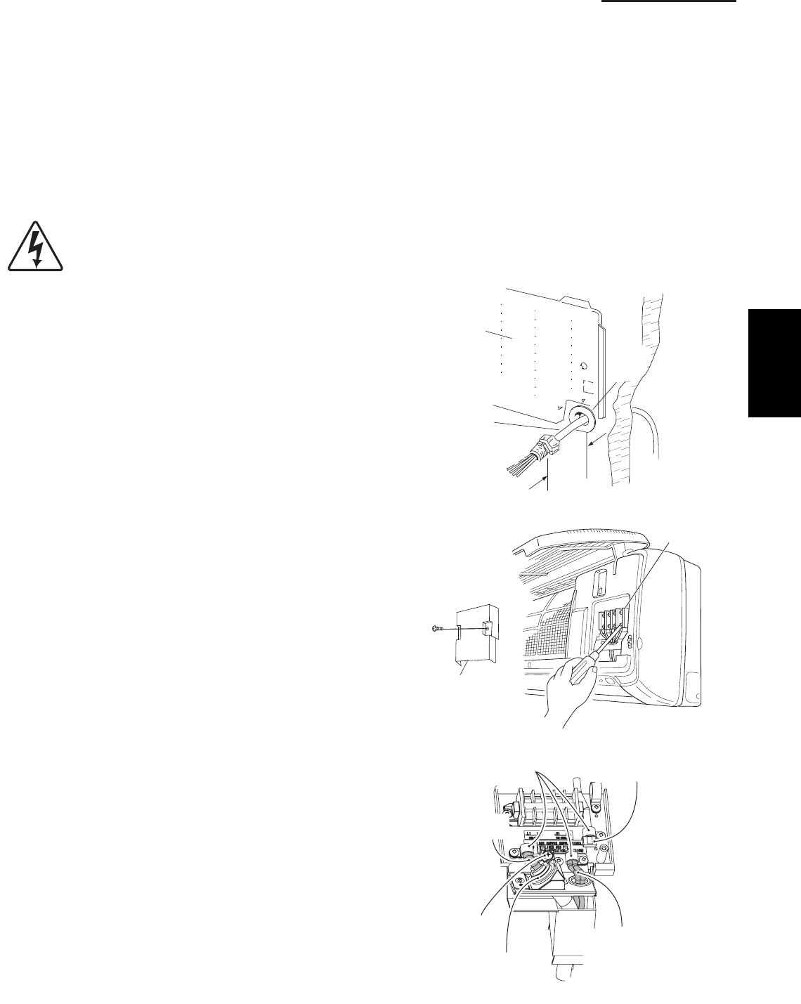
6-16. Wiring Instructions for Inter-Unit Connections
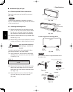
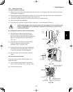
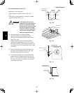
(1) Insert the inter-unit wiring (according to local
electrical codes) into the through-the-wall PVC
pipe. Run the wiring toward the indoor side allowing
approx. 10 inches to extend from the wall face.
(Fig. 1-43)
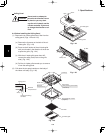
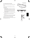
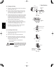
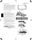
(2) Route the inter-unit wiring from the back of the
indoor unit and pull it toward the front for
connection. (Figs. 1-44a and 1-44b)
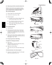
(3) Connect the inter-unit wiring to the corresponding
terminals on the terminal plate (Figs. 1-44a and
1-44b) while referring to the wiring diagram.
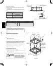
(4) Be sure to secure the wiring with the provided
clamp.
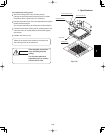
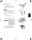
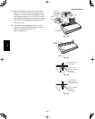
How to remove the cover plate
To access the terminal plate inside the indoor unit,
follow these steps.
(1) Using a Phillips head screwdriver, remove the
screw on the cover plate. (Figs. 1-44a and 1-44b)
(2) Remove the cover plate.
Rear
panel
Wiring
Wall
10 in.
Plastic
cover
Fig. 1-43
Terminal
plate
Cover plate
Fig. 1-44a
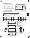
Clamping
strap
Remote control wiring
and Inter-unit control
wiring (field supplied)
Earth screw
Conduit
(field supplied)
Connection for Solenoid
Vale Kit (for 3WAY)
Power wiring
(field supplied)
Fig. 1-44b
1