


6-4
6. Test run
6-4. Items to Check Before the Test Run
(1)
(2)
Turn the breaker ON at least 12 hours in advance in order to energize the crank case heater.
Fully open the closed valves on the liquid tube and gas tube sides.
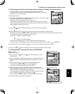
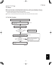
6-5. Test Run Using the Remote Controller
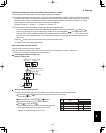
(1) Press and hold the remote controller button for 4 seconds or longer. Then press the button.
• “TEST” appears in the LCD display during the test run.
• Temperature control is not possible when test run mode is engaged.
(This mode places a large load on the devices. Use it only when performing the test run.)
(2)
Note: The outdoor unit will not operate for approximately 3 minutes after the power is turned ON or after it stops
operating.
(3)
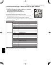
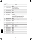
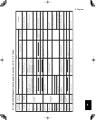
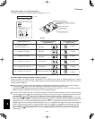
Refer to the “Table of Self-Diagnostic Functions and Corrections” on the next page, and correct the problem.
(4)
button again. Check that “TEST” disappears from the LCD display.
(This remote controller includes a function that cancels test run mode after 60 minutes have elapsed, in order to
prevent continuous test run operation.)
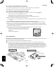
(5)
Use either Heating or Cooling mode to perform the test run.
If normal operation is not possible, a code appears on the remote controller LCD display.
After the test run is completed, press the
For the test run of an inverter outdoor unit, operate the compressors for a minimum of 10 minutes.
* When performing a test run using a wired remote controller,
operation is possible without attaching the cassette-type
ceiling panel.
(“P09” will not be displayed.)
6-6. Precautions
Request that the customer be present when the test run is performed. At this time, explain the operation manual
and have the customer perform the actual steps.
Be sure to pass the manuals and warranty certificate to the customer.
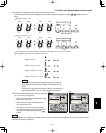
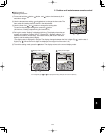
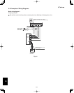
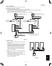
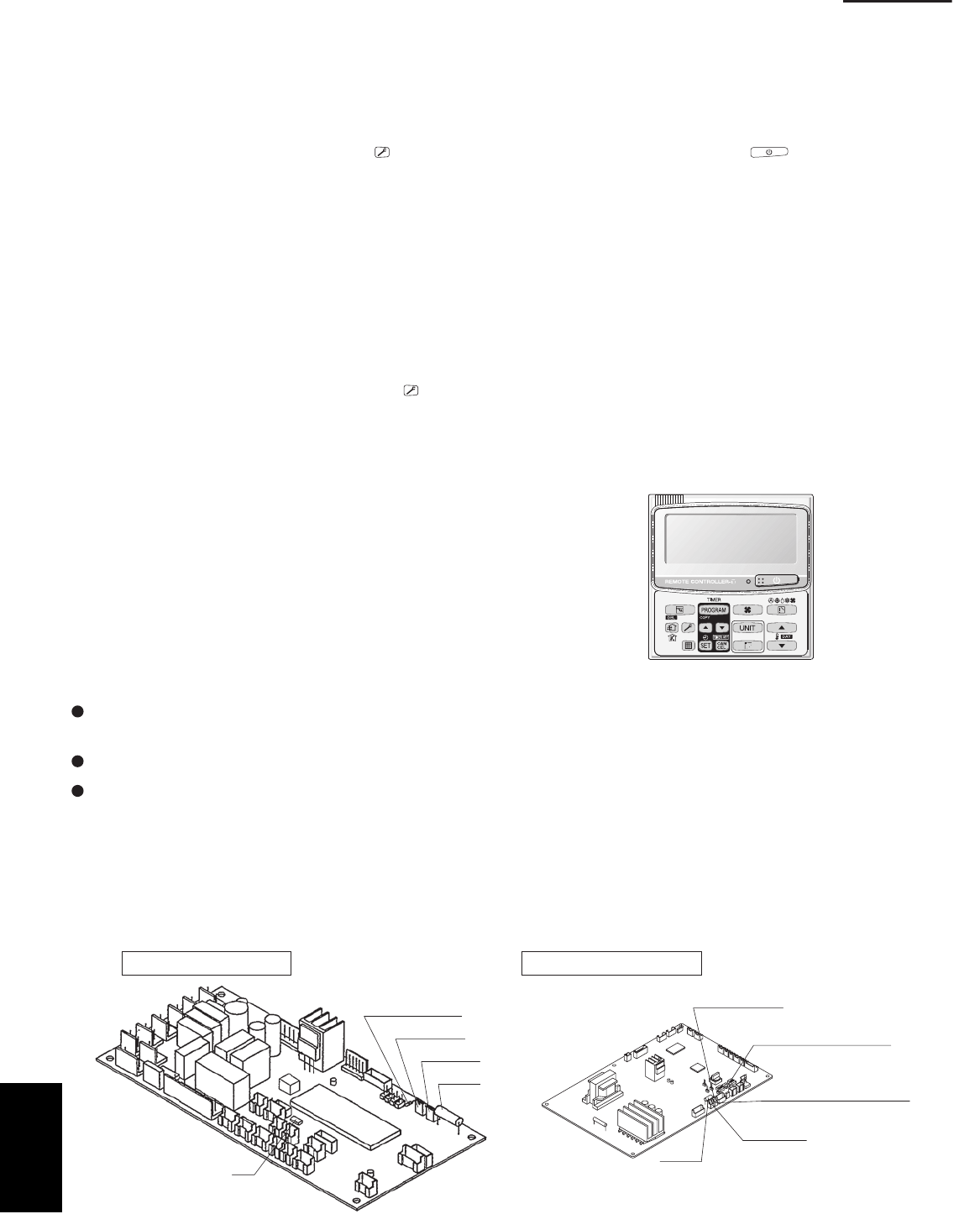
Check that the AC 230 / 208 V power is not connected to the inter-unit control wiring connector terminal.
* If AC 230 / 208 V is accidentally applied, the indoor or outdoor unit control PCB fuse (0.5A for both indoor
and outdoor units) will blow in order to protect the PCB. Correct the wiring connections, then disconnect the
2P connectors (indoor: blue, OC) (outdoor: blue, OC) that are connected to the PCB, and replace them with
2P connectors (indoor: brown, EMG) (outdoor: brown, EMG). (Refer to the figure below.) If operation is still not
possible after changing the brown connectors, try cutting the varistor (VA002) (both indoor and outdoor).
(Be sure to turn the power OFF before performing this work.)
Indoorunit control PCB
Outdoorunit control PCB
IC8
Varistor (black)
Fuse
VA002
CN44 EMG
CN40 OC
VA002 (Varistor)
OC (blue)
connector
0.5A
0.5A
Terminal plug (black)
3 – 5 HP
EMG (brown) connector
Fig. 6-4
Fuse
CZ-RTC2
6