


4-13
4. Service procedures
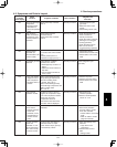
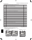
Sensor installation Sensor
Sensor type
Sensor
Sensor type
sserddasserddanoitacol
00 Room temp. 05 –
(temp. used for control)*
01 Remote controller temp. 06 Discharge temp.
Indoor unit 02 Indoor intake temp. 07 –
03 Indoor heat exchanger temp. (E1) 08 –
04 Indoor heat exchanger temp. (E2) 09 –
0A Discharge temp. (TD) 12 –
–31–b0
tnerruC41–C0
(AC current)
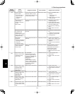
Outdoor unit 0d Intake temp. (TS) 15 Outdoor electronic control
valve position
0E Outdoor heat exchanger temp. (C1) 16 –
0F Outdoor heat exchanger temp. (C2) 17 –
–81–01
11 Outdoor air temp. 19 –
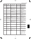
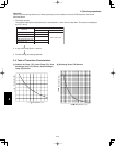
Sensor Temperature Correlation Table
* Main unit only when group control is enabled
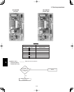
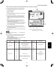
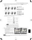
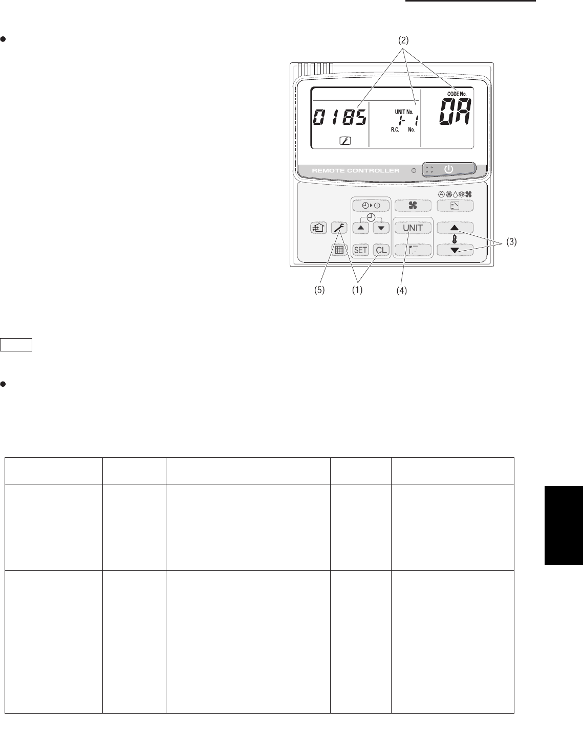
Figure: Sample display when discharge
temperature at unit No. 1-1 is 185˚F
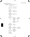
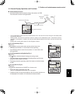
Sensor Temperature Display Function (Displayed both when operating and stopped)
The below check procedure can be used to display
all remote controller, indoor unit, and outdoor unit
sensor temperatures.
<Check procedure>
(1) Press and hold the button and button simultaneously
for 4 seconds or longer.
(2) Unit No. X-X (main unit No.), item code XX (sensor
address), and service monitor 00XX (sensor tem-
perature) appear on the remote controller LCD. (See
figure.)
(3) Press the temperature setting and buttons and
change the item code to the sensor address of the
sensor that you want to monitor.
(For the relationship between the sensor address and
the sensor type, refer to the below Sensor Tempera-
ture Correlation Table.)
(4) During group control and simultaneous operation
multi control, press the button and change to the unit
that you want to monitor.
(5) Press the button to return to normal remote controller
operation.
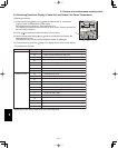
NOTE
The temperature display reads “- - - - ” for units that are
not connected.
If monitor mode is selected during normal operation,
the only parts of the LCD that change are those
shown in the figure.
All other displays do not change, and remain as they
were during normal operation.
4