


4-4
4. Service procedures
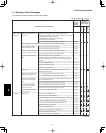
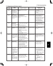
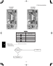
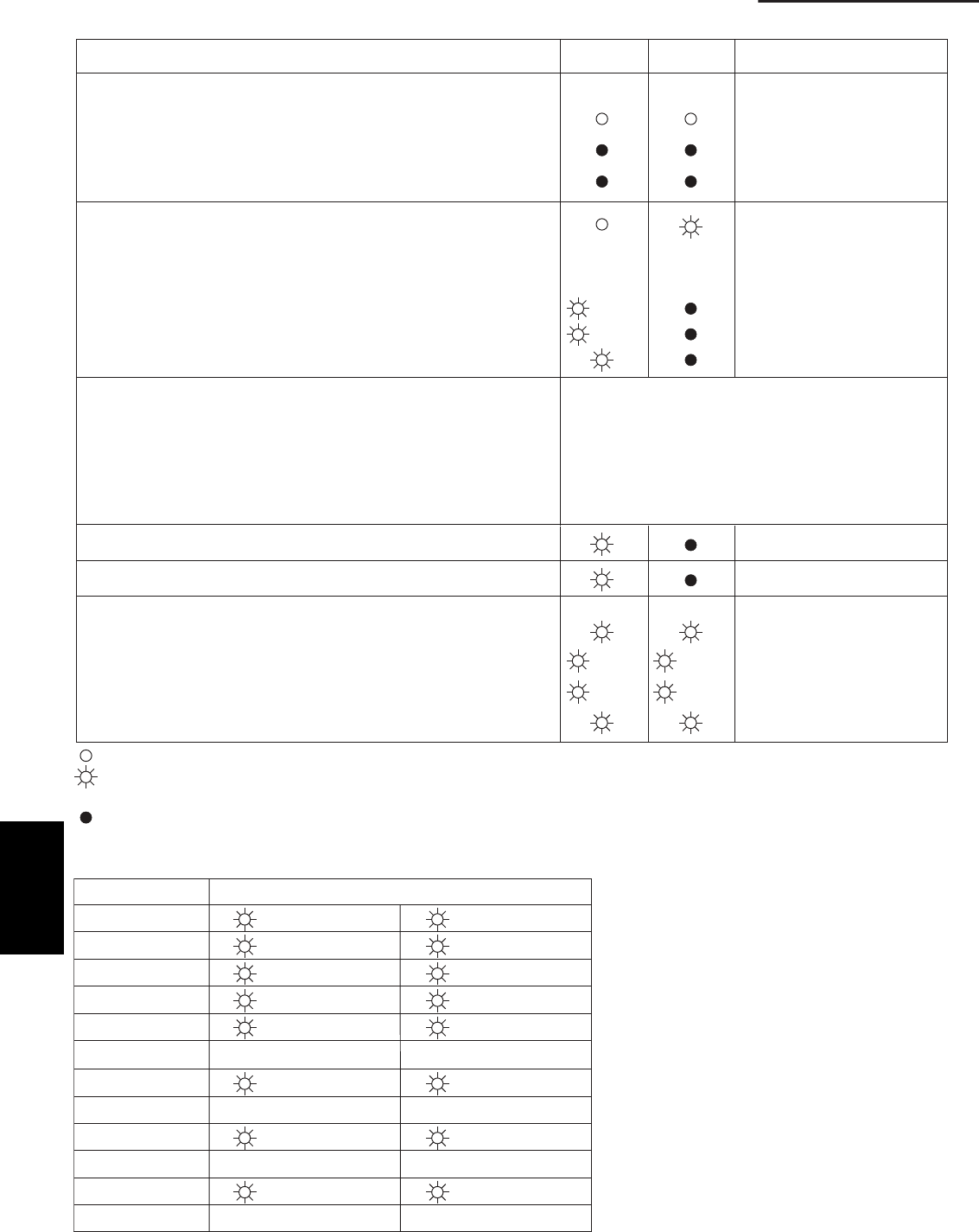
(2) LED Indicator Messages on Outdoor Control PCB
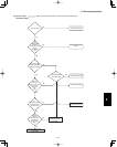
Power ON sequence
1. No communication from indoor units in system
2. Communication received from 1 or more indoor units in system
3. Regular communication OK (Capacity and unit quantity match)
If it is not possible to
advance to 3, repeats 1 → 2.
At 3, changes to normal
control.
P03
Normal operation
Automatic address setting in progress
Automatic address setting alarm (E15)
Automatic address setting alarm (E20)
Automatic address setting alarm (Other than E15 and E20)
EEPROM error (F31)
Blinking alternately
Blinking simultaneously
Blinking simultaneously
Blinking simultaneously
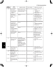
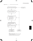
Alarm
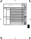
LED 1 blinks M times, then LED 2 blinks N times.
The cycle then repeats.
M = 2: P alarm
6: L alarm
N = Alarm No.
* Refer to
“
1. Examples of alarm display
”
below.
3: H alarm 4: E alarm 5: F alarm
Alternate blinking during alarms
Insufficient gas indicator
Refrigerant recovery mode
Automatic address setting
Displayed during automatic
address setting 1 and initial
communication. After these are
completed, alarm F31 is displayed.
Pre-trip (P20)
Pre-trip (insufficient gas)
Pre-trip (other)
(0.25/0.75)
(0.75/0.25)
(0.25/0.75)
(0.75/0.25)
(0.25/0.75)
(0.75/0.25)
ON
:
:
:
LED 1 LED 2 Remarks
OFF
Blinking (0.25/0.75) indicates that the lamp illuminates for 0.25 seconds, and then is OFF for 0.75 seconds.
Unless otherwise indicated, the blinking is (0.5/0.5).
Note:
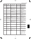
This table shows example alarms. Other alarms
may also be displayed.
P03
P04
P05
P31
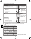
H01
•
E04
•
F07
•
L13
•
( Blinks 2 times )
(
"
)
(
"
)
(
"
)
(Blinks 3 times)
•
(Blinks 4 times)
•
(Blinks 5 times)
•
(Blinks 6 times)
•
(Blinks 3 times)
(Blinks 4 times)
(Blinks 5 times)
(Blinks 31 times)
(Blinks 1 times)
(Blinks 4 times)
(Blinks 7 times)
(Blinks 13 times)
Alarm / Display LED 1 Alternately
→
→
LED 2
(3) Examples of alarm display (other than E15, E16, and E20)
4