


2-10
2. Processes and functions
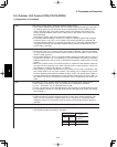
Push-button switch (black): Automatic address setting switch
• If the system address switch (S002: set to 0 at time of shipment) setting is other than
"0" (central control), press this switch once to automatically set the addresses at all
indoor units which are in the same system, and are connected to that outdoor unit.
During automatic address setting, the 2 LEDs (red) on the outdoor unit control PCB
blink alternately.
(Pressing this switch again stops automatic address setting.)
• If automatic address setting is currently in progress at another system that is subject
to central control, only LED 1 on the outdoor unit control PCB blinks to indicate that
automatic address setting is in progress at another unit. If automatic address setting is
in progress at another unit, automatic address setting cannot be started at this unit,
even if S001 is pressed.
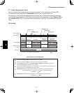
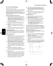
Rotary switch (10 positions, black): System address setting switch
• This switch is set to 0 (1 system control) at the time of shipment. However the address
for each system must be set when multiple systems are controlled or when central
control is used. (Figure 1)
• If the system address is set to 0, automatic address setting is started when the power is
turned ON. Therefore it is not necessary to use switch SW01 and perform automatic
address setting in the case of single or simultaneous-operation multi control of a single
system.
• When using central control for multiple systems, a maximum of 30 systems (maximum
64 units) can be connected. In the case of group control or central control, set the sys-
tem address to a setting other than 0 (1 or above).
• If the number of systems is greater than 9, this switch can be used in combination with
DIP switch S003 to set up to 30 systems. The setting can be made as high as 39,
however all settings above 30 are handled as 30 for control. (For details, refer to Table 1.)
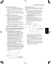
• If system addresses are duplicated (the same address exists more than once), LED 1 on
the outdoor unit control PCB lights up, and alarm "L04" is displayed on the remote con-
troller.
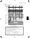
DIP switch (2P, blue): System address 10s-digit and 20s-digit place setting switch
• When setting 10 systems or more, set this switch in combination with S002.
• For 10 – 19 systems, set 1P (10s-digit place) to ON.
• For 20 – 29 systems, set 2P (20s-digit place) to ON, and set 1P (10s-digit place) to OFF.
• For 30 systems, set both 1P (10s-digit place) and 2P (20s-digit place) to ON. (For details,
refer to Table 1.)
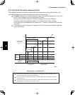
Refrigerant recovery switch (red button switch)
• Press this switch to perform refrigerant recovery control using cooling operation. The
indoor unit fan will operate at HIGH and 55 Hz for a maximum of 10 minutes. When
refrigerant recovery is completed, close the valves and press this switch to stop the
operation.
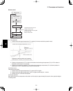
2P plug (red): Pin used for PCB inspection at the factory
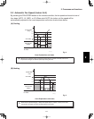
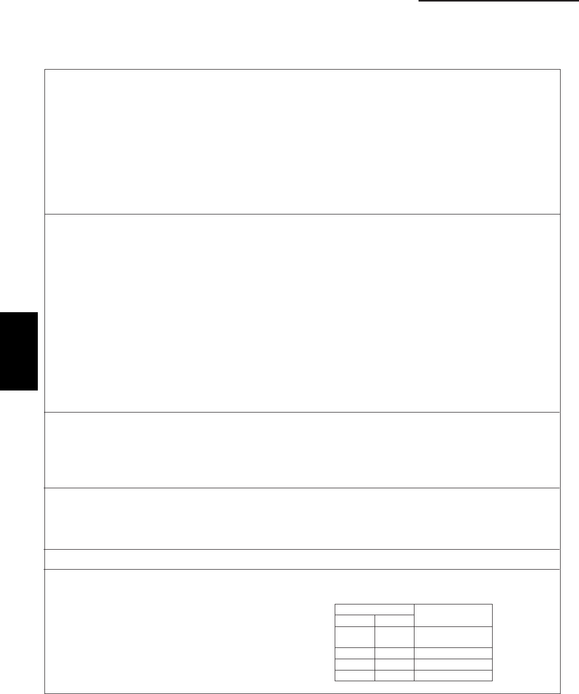
3P plug (red): Can be used for demand control
• The operating ranges are shown in the table.
Test (CN036)
EXCT (CN026)
S001
S002
S003
S005
2P and 3P 1P and 3P
Operating
range
0
0
1
1
0
1
0
1
normal (at shipment
from factory)
rated capacity
70%
0%
Short-circuited
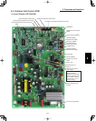
2-6 Outdoor Unit Control PCB (CR-CH4272R)
(1) Explanation of Functions
2