


5-3
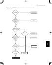
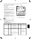
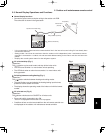
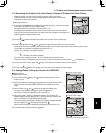
5. Outdoor unit maintenance remote control
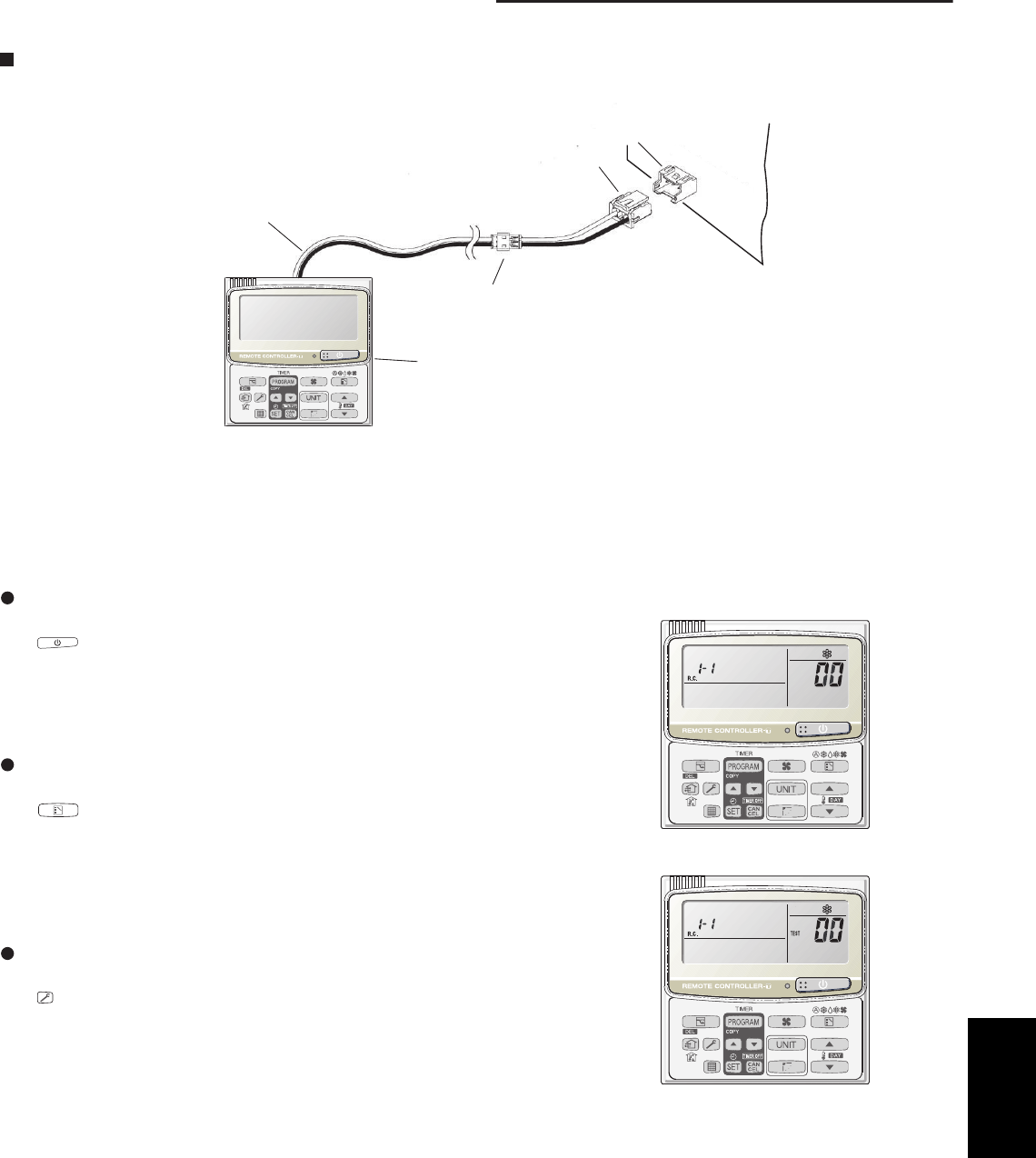
Remote controller Assy
Special service checker wiring
Relay connector (2P, white)
PCB connector
(3P, blue)
RC (3P, blue)
Outdoor
unit PCB
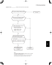
5-3. Normal Display Operations and Functions
Normal display functions
• Connect the special service checker wiring to the outdoor unit PCB.
The connection is shown in the figure below.
* It is not necessary to disconnect the communications line in the inter-unit control wiring if it has already been
connected at this time.
* Setting modes 1 and 2 can be used even when the outdoor unit is independent (when 1 maintenance remote
controller is connected to 1 outdoor unit and automatic address setting for the indoor units has not been com-
pleted).
* Displays the overall system status for that refrigerant system.
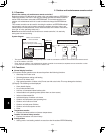
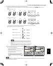
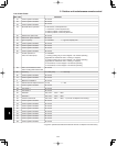
All units start/stop (Fig. 1)
<Operation>
The button can be used to start and stop all the indoor units.
• The LED turns ON when 1 or more indoor units is operating.
• The LED blinks when an alarm has occurred at 1 or more indoor units
during operation.
Switching between cooling/heating (Fig. 1)
<Operation>
The
button switches between heating and cooling modes.
• The specifications are equivalent to the heating/cooling input that was
present on earlier outdoor unit PCBs.
• The display shows the operating mode of the indoor unit with the lowest
number.
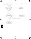
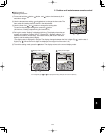
All units test run (Fig. 2)
<Operation>
The button switches test run ON/OFF for all indoor units.
• Press and hold for 4 seconds to turn ON.
“Test run” is displayed while the test run is in progress.
• Conditions of test runs that are started from the unit remote controller are
not displayed on the outdoor unit maintenance remote controller.
Fig. 1
Fig.2
5