257
FX3S/FX3G/FX3GC/FX3U/FX3UC Series
Programming Manual - Basic & Applied Instruction Edition
9 Move and Compare – FNC 10 to FNC 19
9.6 FNC 15 – BMOV / Block Move
1
Introduction
2
Overview
3
Instruction
List
4
Devices
in Detail
5
Specified the
Device &
Constant
6
Before
Programming
7
Basic
Instruction
8
FNC00-FNC09
Program Flow
9
FNC10-FNC19
Move & Compare
10
FNC20-FNC29
Arith. & Logic
Operation
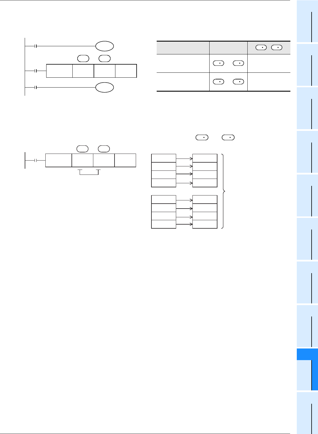
Extension function (bi-directional transfer function)
By controlling the direction inverse flag M8024
*1
for BMOV (FNC 15) instruction, data can be transferred in two
directions in one program.
*1. M8024 is cleared when the PLC mode is changed from RUN to STOP.
Caution
When specifying digits of bit devices, specify the same number of digits for and .
BMOV direction inverse
flag
Transfer
direction
,
M8024
*1
: OFF
→
D5 → D10
D6 → D11
D7 → D12
M8024
*1
: ON
←
D5 ← D10
D6 ← D11
D7 ← D12
X000
FNC 15
BMOVP
D5 D10 K3
X001
M8024
BMOV
direction
inverse flag
M8001
M8024
BMOV
direction
inverse flag:
OFF
Normally OFF
during operation
n
*1
*1
S
D
S
D
S D
S D
S
D
n
n = 2
Y000
Y001
Y002
M 0
M 1
M 2
M 3 Y003
Y004
Y005
Y006
M 4
M 5
M 6
M 7 Y007
Specify the same number
of digits.
(Example: K1)
M8000
FNC 15
BMOV
K1M0 K1Y000 K 2
S D


