132
FX3S/FX3G/FX3GC/FX3U/FX3UC Series
Programming Manual - Basic & Applied Instruction Edition
4 Devices in Detail
4.9 Data Register and File Register [D]
4.9.3 Functions and operation examples of data registers
Data registers are devices for storing numeric data.
Each data register stores 16-bit data (whose most significant bit specifies the positive or negative sign). Two data
registers combined can store 32-bit numeric data (whose most significant bit specifies the positive or negative sign).
1. General type and latched (battery backed) type data registers
• Once data is written to a data register it does not change unless other data overwrite it.
When the PLC mode switches from "RUN" to "STOP" or when the power is interrupted, however, all data stored in
general type data registers is cleared to "0".
If the special auxiliary relay M8033 has been driven in advance, data is held even when the PLC mode switches
from "RUN" to "STOP".
• Latched (battery backed) type data registers hold their contents even when the PLC mode switches from "RUN" to
"STOP" or when the power is interrupted.
In FX
3U/FX3UC PLCs, the contents of data registers are backed up by the battery built into the PLC.
In FX
3S/FX3G/FX3GC PLCs, the contents of data registers are backed up by the EEPROM built into the PLC. When
the optional battery is installed, the battery backs up the contents of some general type data registers against
power failure.
The contents of data registers are backed up by the battery built in the PLC.
→ For details on each backup method, refer to Section 2.6.
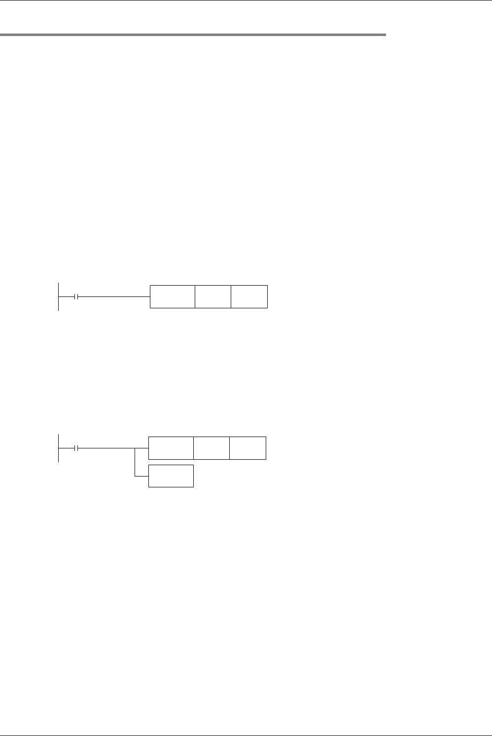
• When using fixed latched (battery backed) type data registers as general type data registers, provide the following
reset circuit by RST or ZRST instruction at the head step in a program.
→ For file registers, refer to Subsection 4.9.4.
2. Special type data registers
• Special type data registers contain informative, special purpose data and are sometimes written to during program
operation.
The contents of special type data registers are cleared to their initial values when restoring the power.
(Generally, these data registers are cleared to "0" at first, and then the initial values (if there are any) are written by
the system ROM.)
• For example, the watchdog timer time is set initially to D8000 by the system ROM. When changing the contents,
write a desired time to D8000 by transfer instruction MOV (FNC 12).
→ For the data backup characteristics of special data registers, refer to Section 2.6 and Chapter 37.
→ For the types and functions of special data registers, refer to Chapter 37.
M8002
Initial pulse
FNC 40
ZRST
D512 D999
Data stored in D512 to D999 are
cleared to "0".
Ex. FX3U/FX3UC PLCs
M8002
Initial pulse
FNC 12
MOV
K250 D8000
FNC 07
WDT
The watchdog timer is set to 250 ms.
The watchdog timer is refreshed.


