


101
FX3S/FX3G/FX3GC/FX3U/FX3UC Series
Programming Manual - Basic & Applied Instruction Edition
4 Devices in Detail
4.5 Timer [T]
1
Introduction
2
Overview
3
Instruction
List
4
Devices
in Detail
5
Specified the
Device &
Constant
6
Before
Programming
7
Basic
Instruction
8
FNC00-FNC09
Program Flow
9
FNC10-FNC19
Move & Compare
10
FNC20-FNC29
Arith. & Logic
Operation
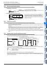
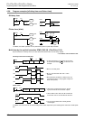
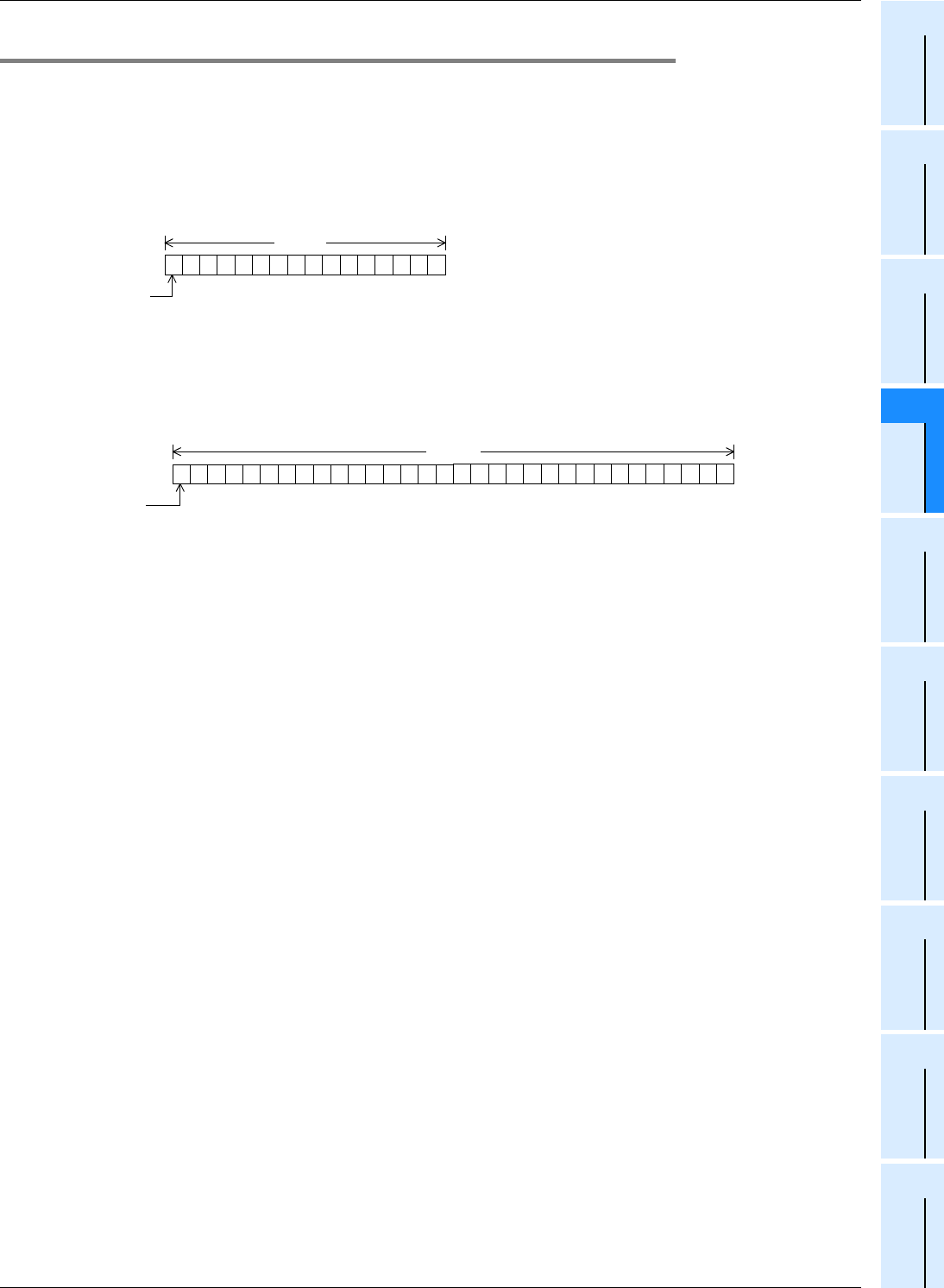
4.5.7 Handling timers as numeric devices
In timers, the output contact operating in accordance with the set value is used in some cases, and the present value
is used as numeric data for control in other cases.
The figures below show the structure of the timer present value registers. When a timer number is specified in an
operand of an applied instruction, the timer is handled as a device storing 16-bit or 32-bit data in the same way as data
registers.
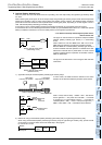
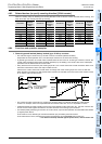
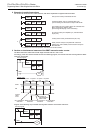
1. Structure of timer present value register
1) 16-bit
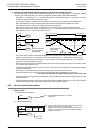
2) 32-bit
2. Use examples in applied instructions
For the full use of timers as numeric devices, refer to the explanation of applied instructions later.
1010101010101010
1
2
4
8
16
32
64
128
256
512
1024
2048
4096
8192
16384
b15
Sign
0: Positive
number
1: Negative
number
*1
b0
High
order
Low
order
16 bits Available numeric value range
16-bit : 0 to 32,767
32-bit : -2,147,483,648 to +2,147,483,647
*1 The sign is valid only when a timer is handled as a substitute for data register.
0000111100001111
1
2
4
8
16
32
64
128
256
512
1024
2048
4096
8192
16384
b31 b0
High
order
32 bits
1010101010101010
32768
65536
131,072
262,144
524,288
1,048,576
2,097,152
4,194,304
8,388,608
16,777,216
33,554,432
67,108,864
134,217,728
268,435,456
536,870,912
1,073,741,824
Sign
0: Positive
number
1: Negative
number
Low
order