


4
LED
S
TATUS
I
NDICATORS
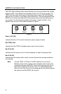
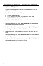
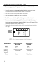
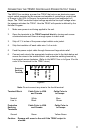
The LED, (light emitting diode) status indicators are found just below the voltage
selector switch. They indicate the operating state of the 12V power supply, the
TRIAC and the status of the sensor and sensor alarm inputs. An LED will glow
when a circuit is active. From these visual indications, it can be determined if the
MX001 box is active and what action the scanner and sensor are performing in
your system. The following list explains the function of each indicator. They
appear inside the box in the order illustrated in Figure 2.
Green +12V (D1)
Indicates that the +12V control and sensor power supply is active
Red TRIAC (D2)
Indicates that the TRIAC switched power output circuit is active.
Red S IN (D3)
Indicates that the sensor circuit is active because an object is being sensed.
Red A IN (D4)
Indicates that the sensor alarm circuit is active because the sensing conditions
are marginal.
Note: The red TRIAC, S IN and A IN LED’s perform two functions.
Besides circuit activity (status), these indicators also monitor the
connection between the MX001 box and the scanner and will not
light if that connection is broken. Thus, if lit, the indicators also
show the user that the inter-connecting signal (link) cable between
the scanner and the MX001 box is good.
D1
C
D2
C
D3
C
D4
C
12V TRIAC S IN A IN
Fi
g
ure 2