


28
S
ENSOR
S
UPPORT
“Universal” Self-contained Sensors That Provide Single
Pole/Double Throw (SPDT) Relay Outputs for Both Object Sensing
and Sensor Alarm
12. Determine from the literature supplied with your sensor which sensor alarm
relay output makes contact with its common terminal when sensing
conditions become marginal. If the output cannot be deter-mined, go on to
Step 13. Otherwise, skip to Step 14.
13. Temporarily apply power to the MX001 box again to activate the sensor
and try to make sensing conditions marginal by placing the object to be
sensed at a greater than normal distance from the sensor or misalign the
sensor to activate the sensor’s alarm output. (Most sensors have a small
indicator that shows when the alarm output is active by being either on or
off depending upon the type of sensor.) Determine with a continuity tester
or ohm meter which relay output (the normally closed [NC or the normally
open {NO] output) makes contact with the COMMON terminal when the
sensor indicates that its alarm output is active.
14. Remove any power applied to the MX001 box (in Step 13) and connect and
secure the “alarm” relay output wire previously determined to the A IN-
terminal. (The other alarm relay output wire may be cut off or connected to
the MX001 COMMON terminal if desired.)
15. Secure the cable by turning the strain relief’s domed sealing nut clockwise
until tight.
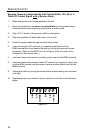
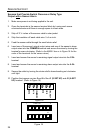
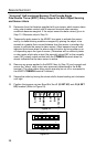
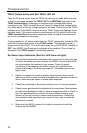
16. Position the jumpers on pins 5 and 6 of the J1 (S SET UP) and J2 (A SET
UP) headers (Refer to Figure 25).
1
2 3 4 5
6
1
2 3 4 5
6
1 A SET UP 6
Figure 25
1 S SET UP 6
J2
J1
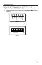
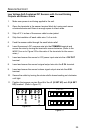
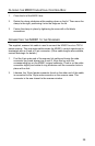
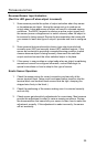
S IN
-
S IN+
+12V OUT
Fi
g
ure 24
A IN+
A IN-
COMMON