


23
S
ENSOR
S
UPPORT
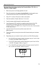
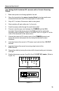
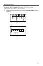
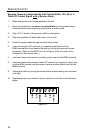
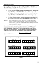
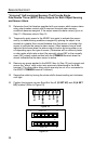
Sensors Powered Independently that Provide Either 12V, 5V or a
10mA DC Output Signal with a Sensor Alarm
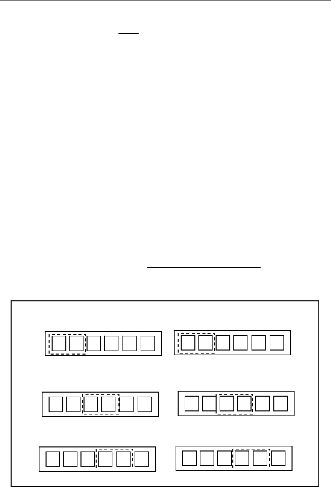
• For 12V DC output signals, position the jumpers on pins 1 and 2 of the
J1 (S SET UP) and J2 (A SET UP) headers. (Refer to Figure 17)
• For 5V DC output signals, position the jumpers on pins 3 and 4 of the
J1 (S SET UP) and J2 (A SET UP) headers. Refer to Figure 17)
• For 10mA DC output signals, position the jumpers on pins 4 and 5 of
the J1 (S SET UP) and J2 (A SET UP) headers. (Refer to Figure 17)
Caution: When configured for a 10mA DC source input, the MX001 box
expects a current limited 10 mA DC signal to be supplied by the
sensor. Failure to limit this current to 10 mA can damage the sensor
input circuitry of the system.
Current limiting can be accomplished by using external limiting resistors of
an appropriate value (which are dependent upon the sensor’s DC signal
output voltage level). One resistor is connected between the S IN+ input of
the MX001 box and the sensor. The other resistor is connected between the
A IN+ input of the MX001 box and the sensor (for the sensor alarm circuit).
Sensor Output Voltage – 3V
Approximate Resistance = 10 mA
1
2
3 4
5
6
1
2
3 4
5
6
1
2
3 4
5
6
1
2 3 4 5
6
1
2 3 4 5
6
1
2 3 4 5
6
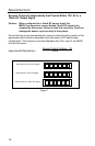
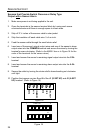
If the source is a 12 V DC Signal:
1 A SET UP 6
1 A SET UP 6
1 A SET UP 6
J2
J2
J2
1 S SET UP 6
1 S SET UP 6
1 S SET UP 6
J1
J1
J1
Fi
g
ure 17