


3
I
NTERNAL
C
OMPONENTS
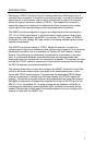
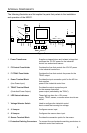
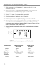
The following illustration and list explain the parts that pertain to the installation
and operation of the MX001.
1. Power Transformer Supplies a stepped down and isolated voltage that
produces the 12V DC power for the industrial
control box and external sensor.
2. F2 Control Fuse Holder Contains the fuse that controls the 12V DC power
in the industrial control box.
3. F1 TRIAC Fuse Holder Contains the fuse that controls the power for the
TRIAC output.
4. Power Terminal Block Provides the input connection point for the AC line
that supplies
(Line Power Input) power to the industrial control box.
5. TRIAC Terminal Block Provides the output connection point
for the scanner controlled.
(Controlled Power Output) power output (switched by the TRIAC).
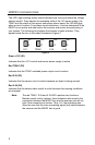
6. LED Status Indicators These light up when the +12V power
supply, TRIAC, sensor, or sensor alarm circuits are
active.
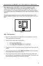
7. Voltage Selector Switch Used to configure the industrial control
box to match the incoming line voltage.
8. J1 Jumper Configures sensor input.
9. J2 Jumper Configures the sensor alarm input.
10. Sensor Terminal Block Provides the connection points for the sensor.
11. Protective Earthing Connectors To connect line cord protective earthing conductors to
industrial control box enclosure.
115V
230V
F1
TRIAC
F2
Control
Neutral
Line in
Neutral
Triac out
A In+
A In-
Common
S IN-
S in+
+12V Out
D1
C
D2
C
D3
C
D4
C
12V Triac S IN A IN
J1
J2
8
9
7
1
2
3
4
5
6
11
10
Fi
g
ure 1