


22
S
ENSOR
S
UPPORT
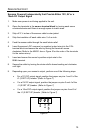
Sensors Powered Independently that Provide Either 12V, 5V or a
10mA DC Output Signal with a Sensor Alarm
1. Make sure power is not being applied to the unit.
2. Open the terminals in the sensor terminal block by turning each screw
counterclockwise until there is enough space to insert wires.
3. Strip off 2 ¼ inches of the sensors cable’s outer jacket.
4. Strip the insulation off each cable wire ¼ of an inch.
5. Feed the sensor cable through the small strain relief.
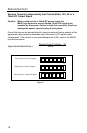
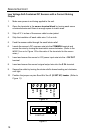
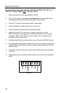
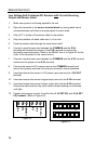
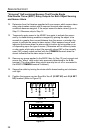
6. Insert the sensor’s DC common (or negative) output wire into the
S IN- terminal block and secure the wire by turning the terminal’s screw
clockwise. (Refer to the MX001 box or to Figure 16 for the order of the
terminals for the sensor wires.)
7. Insert and secure the sensor’s positive output wire into the S IN+ terminal.
8. Insert and secure the sensor’s alarm DC common (or negative) output wire
into the A IN- terminal and the sensor’s alarm positive output wire into the
A IN+ terminal.
9. Secure the cable by turning the strain relief’s domed sealing nut clockwise
until tight.
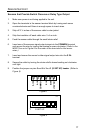
10. Depending upon your sensor’s output, perform one of the of the following
steps:
S IN-
S IN+
+12V OUT
Fi
g
ure 16
A IN+
A IN-
COMMON