


7
Installation of Venting for Outdoor
Units
WARNING
Do not install units in locations where flue products
can be drawn into adjacent building openings such
as windows, fresh air intakes, etc. Distance from
vent terminal to adjacent public walkways, adjacent
buildings, operable windows, and building openings
shall conform with the local codes. In the absence
of local codes, installation shall conform with the
National Fuel Gas Code, ANSI Z223.1, or the CAN/
CGA B-149 Installation Codes.
WARNING
The following guidelines must be followed for all
outdoor units:
1. Building materials that will be affected by flue
gases should be protected.
2. Maintain minimum horizontal clearance of 4 feet
from electric meters, gas meters, regulators,
and relief equipment. In Canada, the minimum
clearance is 6 feet.
3. The combustion blower discharge on outdoor
units must be located a minimum of 42 inches
from any combustible materials.
4. Do not modify or obstruct the combustion
air inlet cover or the combustion blower
weatherhood.
5. Do not add vents other than those supplied by
the manufacturer.
6. During the winter, keep the unit clear of snow to
prevent any blockage of the combustion venting.
1. Follow Guidelines
All of the following guidelines must be followed when
installing the unit.
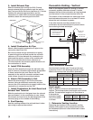
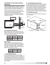
2. Install Stack (Optional)
Clearance may require an exhaust stack. Install an
exhaust stack as needed to the exhaust connection
on the unit. Install a vent terminal on the exhaust pipe.
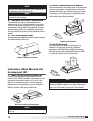
Installation of Evaporative Cooling
Module (optional)
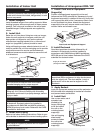
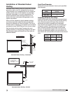
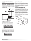
1. Locate Equipment Support(s)
Position equipment support(s) on the roof (reference
the CAPS submittal for
placement of equipment
support(s) in relation to
the unit). Verify that all unit
supports are level, shim if
necessary. Attach equipment
support to the roof, remove
metal cover, flash to wooden nailer and
reinstall cover.
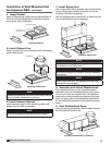
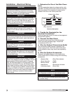
2. Apply Sealant
Apply an appropriate sealant around the
airstream opening to create an air tight
seal.
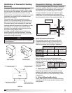
3. Set Evaporative Cooling Module
Use a crane and a set of spreader bars hooked to the
factory lifting lugs
to lift and center
the module on the
equipment support(s).
The flange on the
evaporative cooler
should overlap the
flange on the unit.
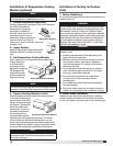
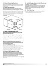
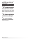
4. Secure Cooling Module to Unit
Use self-tapping screws to fasten the cooling module
to the base unit along the
top and down both sides.
Fasten at the top through
the flanges. To fasten the
sides, the media must
be removed. To remove
the media, first remove
the access panel on
the evaporative module
and disconnect the evaporative pump(s). The media
will now slide out. With the media removed, you can
access the side fastening points inside the evaporative
module. With all the screws in place, reinstall the media,
reconnect the pumps and reinstall the access panel.
NOTE
Small evaporative coolers ship attached to the base
unit and require no additional mounting.
NOTE
The use of all lifting lugs and a set of spreader bars is
mandatory when lifting the evaporative cooling module.
NOTE
When mounting the evaporative cooler, it is
important that it is level to ensure proper operation
and water drainage.
Metal Cover
Equipment
Support
Roof Curb
Equipment Support
Sealant
Sealant
Placing Evaporative Module
Securing Evaporative Module
®
Model IG / IGX Make-Up Air