


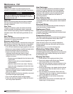

64
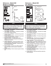
Reference - Model IG
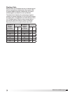
(8:1 Staged)
1
2
7
8
9
15
4
6
14
5
12
21
23
25
3
10
11
13
16
17
18
18
19
20
22
24
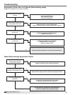
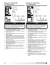
NOTE
This is a typical blower control center, the control
center in your unit may be different. Reference the
ladder diagram on the inside of the control center
door for a unit specific wiring diagram.
1. Supply Motor Starter - 24 volt magnetic contacts
for starting supply motor.
2. Supply Overload - Provides electronic overload
protection to supply motor.
3. Low Voltage Transformer - Provides low voltage
to fan/heat/cooling enable controls, staged
furnace controls and optional evaporative cooling
controls.
4. Control Terminal Block - Provides wiring access
to controls.
5. Fan Relay - Allows power to pass to energize
motor starter.
6. Control Terminal Block - Provides wiring access
to fan/heat/cooling enable controls.
7. Auxiliary Contact (Optional) - Provides one
normally closed and one normally open contact
for other equipment.
8. Exhaust Motor Starter (Optional) - 24 volt
magnetic contacts for starting exhaust motor.
9. Exhaust Overload (Optional) - Provides
electronic overload protection to exhaust motor.
10. Exhaust Fuses (Optional) - Provides proper
fusing for exhaust fan motor(s).
11. Building Freeze Protection Timer (Optional)-
Prevents the discharge of cold air into the
building.
12. Heat Relay - Allows power to pass to heating
controls.
13. Low Voltage Transformer - Provides low voltage
to the ignition controller.
14. Heating Terminal Block - Provides wiring access
to heating controls.
15. Inlet Air Sensor (Optional) - Outdoor air stat that
automatically controls the heating and/or cooling
based on outdoor air temperature.
16. Stage Controller - Provides 8 stage control of the
furnace.
17. Airflow Switch - Monitors the airflow inside the
heat exchanger.
18. Ignition Controller - Controls the ignition of the
furnace. Maintains safe operation of the furnace.
19. Evaporative Cooling Fuses (Optional) - Provides
proper fusing to evaporative cooling pump and
controls.
20. Transformer Fuse (Optional) - Provides proper
fusing for evaporative cooling transformer.
21. Cooling Relay (Optional) - Allows power to pass
to cooling controls.
22. Reset Timer (Optional) - Resets cooling system
to run a time interval.
23. Auto Drain Relay (Optional) - Assures supply
pump does not operate during drain interval.
Allows pump to operate in cooling mode.
24. Cooling Timer (Optional) - Allows for automatic
draining of the evaporative cooling system based
on time schedule.
25. Dirty Filter Switch (Optional) - Monitors filter
pressure drop. Turns on indicating light when
pressure drop is above field adjustable set point.
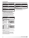
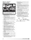
Large
Manifold
Small
Manifold
Gas
Pressure
Test Port
Gas Pressure
Test Port
3/4 inch
Gas Supply
Connection
Staged Gas
Valves
®
Model IG / IGX Make-Up Air