


41
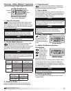
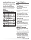
Program Revision Number
To access the program revision number from the default
display, press the Up or Down key until the display reads
F##, J## or I##. The two numbers following the letter
indicate the revision number. For example, F12 indicates
program F, revision twelve.
Optional Room Override (ROt)
When the room override function is triggered, the
discharge air temperature (70ºF default) is temporarily
changed to the room override setting (90ºF default).
When the room override function is released the
discharge air temperature returns to the default
temperature.
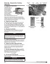
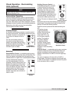
Indicating Lights
Three indicating lights are located across the top of
the display to indicate the status of the furnace.
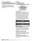
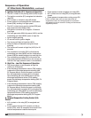
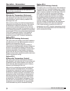
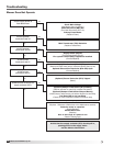
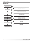
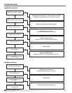
Sequence of Operation
4:1 Electronic Modulation
1. Exhaust Fan Contact (S1) Manually Closed
(optional)
• PowerpassesthroughN.C.contactonexhaustfan
overload (ST2 OL), which is closed if exhaust fan
(M2) has not overloaded
• Powerpassestoexhaustfanstarter(ST2)
• N.O.contactonexhaustfanstarter(ST2)is
energized and closed
• Powerpassestoandenergizesexhaustfan(M2)
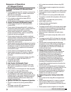
2. Supply Fan Contact (S2) Manually Closed
• PowerpassesthroughN.C.eld-suppliedre
contact (FSC)
• PowerpassesthroughoptionalN.O.contacton
exhaust fan starter (ST2), which is closed when the
optional exhaust starter (ST2) is activated
• PowerpassesthroughN.C.contactonsupply
starter overload (ST1 OL), which is closed if the
supply fan has not overloaded
• PowerpassesthroughN.C.contactonoptional
freeze protection timer (RT4), which is closed if the
temperature has remained above the set point
• Powerpassestoandenergizesoptionalinlet
damper (D1), which opens
• Powerpassesthroughoptionaldamperlimitswitch
(DL1), which is energized and closed if the optional
inlet damper is open. It may take several minutes
for the damper to fully open and for the damper
limit switch to close
• Powerpassestoandenergizesfanrelay(RF)
• PowerpassesthroughN.O.contactonfanrelay
(RF), which is closed once the fan relay (RF) is
activated
• Powerpassestoandenergizesstarterrelay(ST1)
• N.O.contactonsupplyfanstarter(ST1)is
energized and closed
• Supplyfan(M1)starts
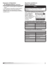
3. Heat Contact (S4) Manually Closed
• PowerpassesthroughN.O.contactonfanrelay
(RF), which is energized and closed if the supply
fan (M1) is on
• Powerpassestoandenergizestheheatrelay(RH)
• N.O.contactonheatrelay(RH)closes
• PowerpassestoN.C.contactonhightemperature
limit control (HLC1), which remains closed if it has
not been tripped
• 24VACissuppliedtoignitioncontroller(IC1)
• Themodulatingcontroller(SC1)comparesthe
inlet air temperature to the inlet air set point (iAS,
FX Program Menu). If the inlet air temperature is
below the set point, the modulating controller (SC1)
closes N.O. contact (FUR 1) and sends a call for
heat to the ignition controller (IC1)
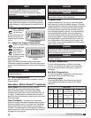
4:1 Electronic Modulation
Light On Off Blinking
L1 Call for Heat No call for heat High fire
L2
Call for heat
sent to ignition
controller
No call for heat
sent to ignition
controller
High fire
L3
Combustion fan
high speed
Combustion fan
low speed
High fire
8:1 Staged Control
(Single Furnace Units)
Light On Off Blinking
L1 Call for heat No call for heat N/A
L2 n/a n/a High fire
L3 Burner interlock n/a n/a
8:1 Staged Control
(Multi Furnace Units)
Light On Off Blinking
L1 n/a n/a n/a
L2 n/a n/a Alarm
L3 Program Mode n/a
Saving new
setting
®
Model IG / IGX Make-Up Air