


42
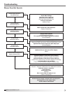
4. Ignition Controller (IC1) Sequence of Operation
• TheN.O.contactonairprovingswitch(PS2)isopen
• Theignitioncontroller(IC1)energizestheinduction
relay (IR)
• N.O.contactoninductionrelay(IR)closes
• Powerpassestoandenergizesthecombustion
blower (CM), sending it to high speed
• TheN.O.contactonairprovingswitch(PS2)and
high pressure switch (PS5) closes
• Theignitioncontroller(IC1)beginsa15second
pre-purge
• Themaingasvalve(MV)fullyopens(100%)andthe
modulating gas valve (MOD) opens to high fire
• Igniterbeginssparking
• 10secondtrialforignitionbegins
• Thefurnacewilllightathighre(100%)
• Whentheameisdetected,theigniterstops
sparking
• Thefurnacewillremainathighre(100%)for30
seconds
• Themodulationcontroller(SC1)willadjustthe
modulating gas valve (MOD) and the combustion
blower (CM) as needed between low and high fire
• Themodulatingcontroller(SC1)willmonitorthe
high pressure switch (PS5) and run the furnace at
low fire if the high pressure switch is not satisfied
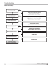
5. High Fire – Low Fire Sequence of Operation
• Thefurnacelightsatandremainsathighre
(100%) for 30 seconds
• Ifthedischargetemperaturesensor(TS2)reading
is above the discharge temperature setting (dtS,
FX Program Menu), and the furnace is not at low
fire, the modulating controller (SC1) will adjust
the modulating gas valve (MOD) down until the
discharge temperature sensor (TS2) reading
equals the discharge temperature setting (dtS, FX
Program Menu)
• Ifthedischargetemperaturesensor(TS2)reading
is below the discharge temperature setting (dtS,
FX Program Menu), and the furnace is not at high
fire, the modulating controller (SC1) will adjust the
modulating gas valve (MOD) up until the discharge
temperature sensor (TS2) reading equals the
discharge temperature setting (dtS, FX Program
Menu)
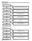
6. Optional Evaporative Cooling Contact (S4)
Closed*
• N.O.contactonfanrelay(RF)isenergizedand
closed
• PowerpassesthroughN.O.contactoninletair
sensor (TS4), which is energized and closed if the
inlet air temperature is above the set point
• Powerpassestoandenergizescoolrelay(RC)
• N.O.contactoncoolrelay(RC)isenergizedand
closed
• Powerpassestoevaporativecoolingpump(P1)
*If DX or chilled water coils are used rather than an
evaporative cooler, the cooling sequence of operation
will depend on the coil controls. Cooling coil controls are
supplied by others.
Sequence of Operation
4:1 Electronic Modulation,
continued
®
Model IG / IGX Make-Up Air